Geometric dimensioning and tolerancing (GD&T)
Any manufacturing processes will always produce parts that have some degree of deviations (errors) from the parts’ nominal design.
Why we need tolerancing?
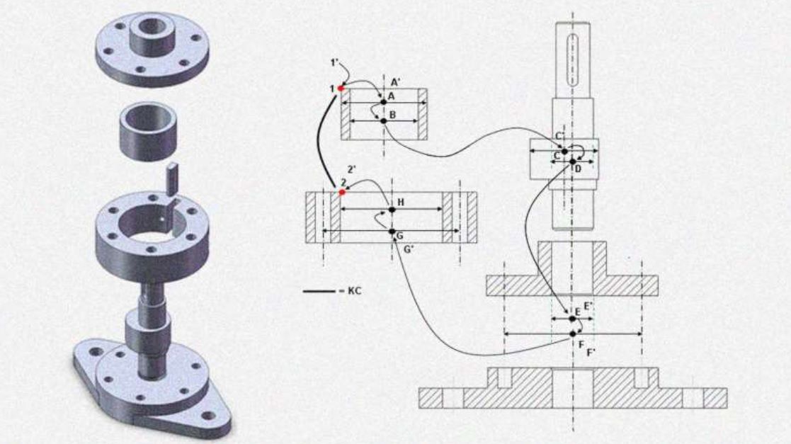
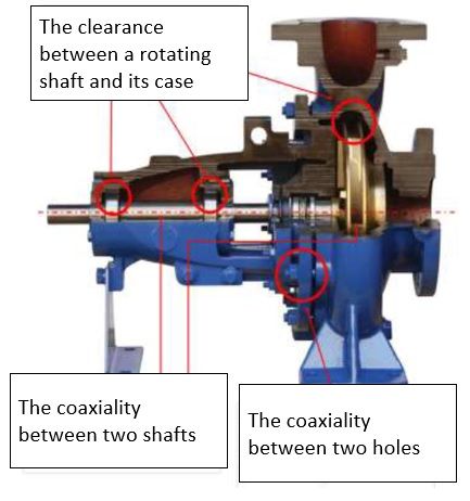
Any manufacturing processes will always produce parts that have some degree of deviations (errors) from the parts’ nominal design. These deviations can be due to variations in manufacturing processes, assembly processes, measurement processes and environment effects, such as vibration and temperature variations. To account for those deviations, tolerances are assigned to each part in its mechanical drawing. The tolerances describe what the allowable deviations of parts can be obtained from manufacturing processes so that the parts can still be assembled to form a product that can function as expected. Figure 1 shows an example of various tolerances assigned to parts on a pump assembly. In Figure 1, a mechanical designer should provide the tolerances of how far the clearance between a rotating shaft and its case, the coaxiality between two shafts and between two holes can be allowed.
+/- tolerance
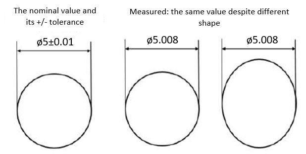
The conventional way to assign tolerance to a part is by using +/- (plus/minus) tolerance. In this way, a designer needs to specify the range of nominal values in the mechanical drawing of the part. This tolerance is self-explanatory, for example, if ones want to tolerance a circle, they can assign the diameter and tolerance as: (5±0.01) mm. This tolerancing means that the circle can be accepted if its measured diameter is between 4.99 mm and 5.01 mm (figure 2).
However, the specified tolerance has an ambiguity. In figure 2 (right), the measured diameter of the circle is 5.008 mm. From this value, we can expect that the circle is within tolerance. But, as can be seen in figure 2 (right), the value can represent two different shapes of the circle depending on where we position our calliper to measure the circle. From the two shapes, only one shape is accepted and the other one is rejected (oval shape). To solve the ambiguity problem, GD&T is proposed.
Why we need GD&T?
GD&T is a design language used by mechanical designers to represent their “design intend” on how a product should be manufactured, assembled and measured so that the product can function as desired. The main advantage of GD&T is that GD&T can comprehensively represent a shape of a product and the relation between features on the product. By this comprehensive representation, GD&T is not ambiguous. It is important to note that GD&T is not replacing +/- tolerance. However, GD&T complement +/- so that any tolerances do not have ambiguity in their interpretation.
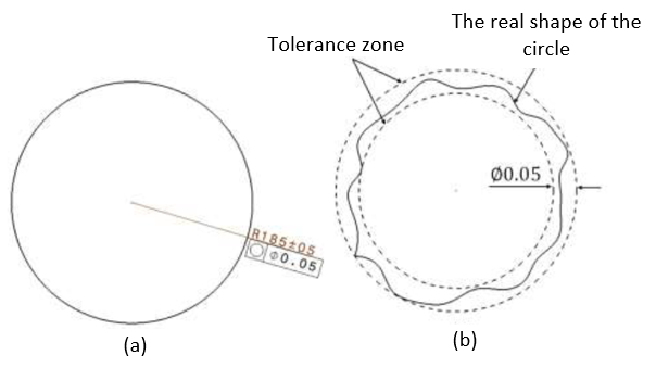
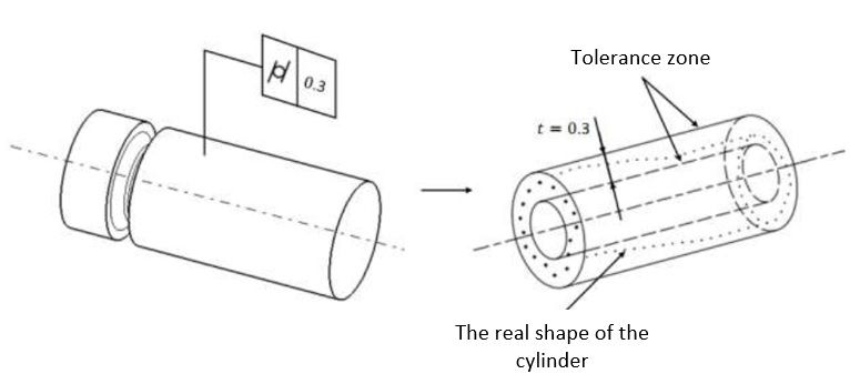
Figure 3 shows an example of specifying tolerance for a circle. The GD&T type used is roundness or circularity. Figure 3 means that the circle is allowed to be in any shapes as long as the shape lies between two concentric circles separated by 0.05 unit distance. This specification is not ambiguous. Another example is a cylindricity tolerance assigned to a cylinder (figure 4). In figure 4, the cylinder is allowed to have any surface shape variations as long as the shape lies between two surfaces of coaxial cylinders separated by 0.3 unit distance.
The de facto standard for GD&T
For GD&T, the current de facto or main reference standard is ASME Y14.5: Dimensioning and Tolerancing: Engineering Drawing and Related Documentation Practices published by The American Society of Mechanical Engineers.
The ASME Y14.5 standard classify the type of GD&T tolerance as:
- Form: straightness, flatness, circularity, cylindricity
- Orientation: angularity, perpendicularity, parallelism
- Location: position, concentricity, symmetry
- Profile: profile of a line, profile of a surface
- Runout: circular runout, total runout
The form tolerance is non-related tolerance and can be defined and verified without a datum. The other types (orientation, location, profile and runout) are related tolerances that require datum for their definitions and verifications.
Further reading can be from a freely downloadable book Toleransi dimensi dan geometri-Analisis rantai variasi dalam proses perakitan produk (in Bahasa).
We sell tutorials (containing PDF files, MATLAB scripts and CAD files) about 3D tolerance stack-up analysis based on statistical method (Monte-Carlo/MC Simulation).