Assembly and tolerancing
Assembly processes are “the moment of truth”. There is none other better phrase to describe assembly processes than the phrase.

Assembly processes are “the moment of truth”. There are no other better phrases to describe assembly processes than this phrase.
Assembly process
The last step of all manufacturing processes to make useful products is assembly. Assembly is a process that combines individual parts or components, either rigid or non-rigid and from micro- to macro-scale sizes, into a final product. The process follows specific pre-determined steps that consider part complexities, human factors, production plans, logistics and organisation structures.
Fundamentally, a single component cannot provide meaningful functionalities if the component is not assembled with other components. A functioning product always in the form of assembled parts. That is why assembly process is very important.
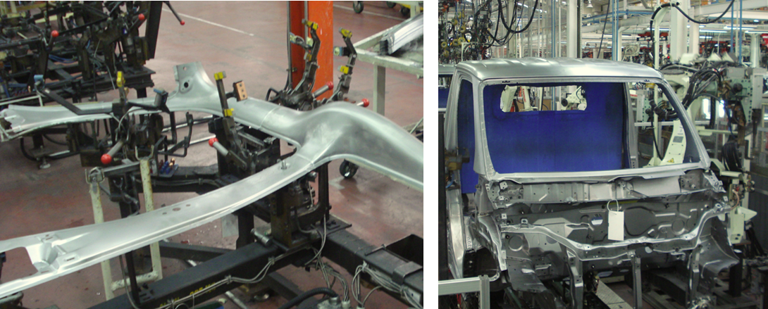
As can be seen from figure 1, a single panel component will not form the body of a car (figure 1 left). Only after assembly from different panels, the body of a car can be formed (figure 1 right).
Assembly process combines both technical (such as component designs and manufacturing processes) and non-technical (such as organisations, human factors and supply chain) aspects. In general, the steps for assembly processes are:
1. Supplying individual parts or components in the right types and quantities
2. Supplying sub-assemblies of components that have been half-assembled from other small components
3. Placing the supplied components or sub-assemblies into a fixturing system
4. Assembling the supplied components and sub-assemblies into a complete assembled product
5. Inspecting the complete product to check that the assembly process is correct
6. Testing the assembled product to verify that the product functions correctly.
The assembly process should be considered from scientific point of view and should follow a systematic approach. We should not think assembly only as a natural process that does not need a systematic approach. Several factors to consider in designing an assembly system are flexibility, generality, adaptability and structure.
An assembly process is the bridge between manufacturing processes and business processes of a company. This bridging means that the design and structure of an assembly process in a company are related to and affected by the business policy of the company.
Examples of the relation between assembly processes and business processes are a company should understand their assembly capacity (ramping up capacity) to decide when a product can be delivered to market within a specific time and a company should understand their assembly capacity to decide whether the company will outsource the assembly process.
An efficient assembly process should have these characteristics:
- Minimising assembly variations (high precision)
- Minimising the need of specialised machine
- Minimising number of required fixtures
- Minimising the need of many skilled operators
- Ability to perform mix production systems
A brief history
After the first industrial revolution (started by the invention of steam engine) in the 18thcentury, the second industrial revolution arose with the invention of electrical power generations and mass production systems with assembly lines.
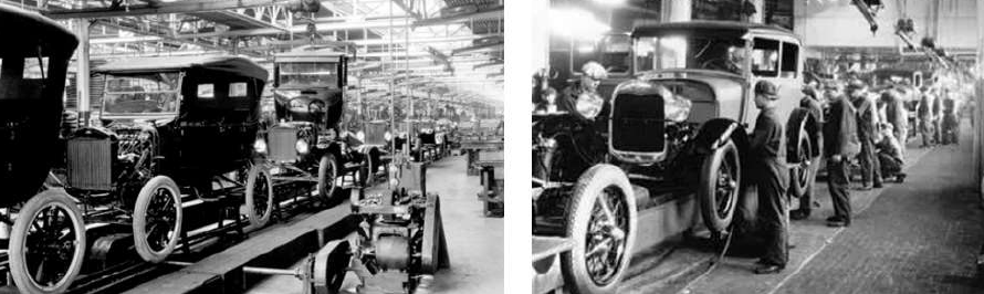
The scientific study for assembly started in 1940 with the era of mass assembly line system proposed by Henry Ford. In this assembly line system, operators stay at their place and parts to be assembled will come by a moving line. Figure 2 shows the example of the assembly line system proposed by Henry Ford. In Figure 2, cars to be assembled are moved by a line system while operators assemble the cars’ components. In this period, the scientific study focused on human factor, but lack of other technical aspect studies, such as fixturing system and numerical analysis, just to mention a few.
In 1950, the third industrial revolution (Digital revolution) started with the invention of fixed- and flexible-automation systems. Fixed-automation system is an automated assembly process for very specific types of products. Meanwhile, flexible-automation system is an automated assembly process that can be implemented to several types of products. These automation systems are supported by emerging micro-processor technologies at that time.
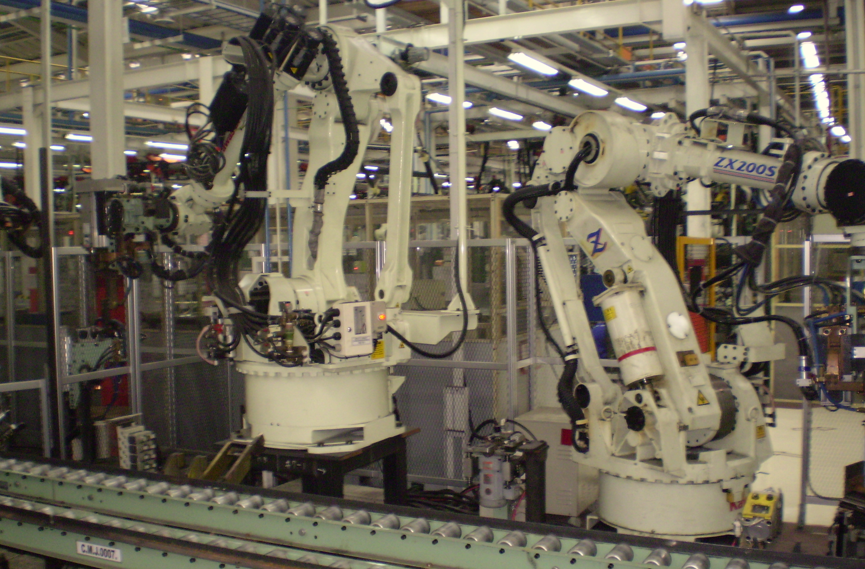
In 1970, flexible robotic assembly systems emerged and significantly improved the productivity of assembly processes. The robotic system can be re-programmed and re-configured within a relatively short time to adapt to different assembly processes. Initially, many of robotics systems are used for spot welding process used for car body assembly. Figure 3 shows the example of a robotic assembly system (that is still used until now) that is used for car body assembly.
Another common automation system used in the third industrial revolution is programmable logic controller (PLC) system. PLC is an industrial automation system that replaces physical mechano-electrical relays, timers and sequencers with virtual relays (software) so that it can be re-programmed for different automation processes.
In the third industrial revolution, technical aspects of assembly process started to be systematically studied. The science of dimensional and geometrical tolerancing (GD&T) emerged. This tolerancing science is motivated by the need of part interchangeability, that is, a product is assembled from many different components manufactured from various different manufacturers.
The fourth industrial revolution (Industry 4.0 or smart manufacturing) emerged in 2013. This revolution is motivated by the concept of cyber-physical system. Cyber-physical system is a system that combines physical, digital and human aspects into an industry. This idea is realised by the emerging new technologies, for example artificial intelligence, collaborative robot, quantum technology, nano technology, internet of things, additive manufacturing and 5G communication system.
Although automation in assembly can improve productivity and has been implemented in many cases, it does not mean that all automated assembly systems are always the best. The reasons are that each product has its own unique assembly process (for example, production volume and cost) or current automation technologies cannot be applied to the assembly process (for example, most mechanical watch assemblies and car body interiors are still done by hand). In general, at the moment, all types of assembly processes, such as manual, fixed- and flexible-automation systems, are still used.
The relation between tolerancing and assembly
The assembly process of a product should be considered and planned from the design phase of the product. Because, the process does not only depend on the geometry of parts but also depend on how the parts are designed (for example, how the parts are connected each other and how to join the parts together).
The most important aspect of a product design that directly has a significant effect on assembly process is dimensional and geometrical tolerancing (GD&T). This tolerancing is given on the nominal dimension of parts on their engineering drawing. In other words, assembly process should be systematically designed and planned from the early phase of a product design.
Assembly processes cannot be separated from dimensional and geometrical tolerancing. Tolerance values assigned to nominal dimensions of the engineering drawing of parts will cause variation propagations from individual features on parts to the final assembly of a product built from these parts.
To design and implement an assembly system, design and manufacturing engineers should understand the main functionality of a product to build and the economic aspect of the product, such as what will the selling price of the product be or how much the budget for the assembly process will be.
Commonly, when there are problems found at an assembly stage (for example the hole of paired bolts and nuts are not centred to each other, the gap of two components is large and a product does not function properly after assembly), most of the time, last assembled parts or previous sub-assembly processes are to blame!
However, the problems can be from incorrect tolerance specifications and allocations given to the feature of the parts.
To understand whether the values of assigned dimensional and geometrical tolerance on parts are correct, we need to do tolerance stack up analysis on the parts. Correct tolerance values mean that when all the parts are made within their tolerances, the parts can be assembled together into an intended product.
Tolerance stack-up analysis is a method to analyse and verify whether parts, manufactured within their tolerance, can be assembled together and function correctly before the parts are manufactured. During the stack-up analysis, tolerance allocation to the parts will be applied before the analysis. Incorrect tolerance allocations will cause the parts cannot be assembled together and function properly even though the parts are manufactured within their given tolerances.
A part designer should effectively and efficiently determine the types and values of tolerance on part drawings. Effective tolerancing means that when parts are manufactured within their tolerance, the parts can be assembled into a functioning product. Efficient tolerancing means that the allocated tolerance value of parts should be optimal such that the values are not too small (causing the manufacturing and inspection cost to be high) or too large (causing high variation on assembled products).
Tolerance stack-up analysis of a product will answer these types of questions, just to mention some:
- Are the tolerance values of parts, such as diameter, flatness, cylindricity and location correct?
- How thin a component still can be manufactured but still within its tolerance limit?
- How large the diameter or centre location deviation of a hole still can be allowed so that the hole still can be assembled with its counter pin?
- Why parts manufactured within their tolerance cannot be assembled together? Or if they can, why the assembled product does not function correctly?
- How large the deviation of dimension and geometric tolerance or parts is still allowed?
- What is the effect of each tolerance value on the final assembled product?
- Whether a size or position tolerance that has the most effect on an assembled product?
Note: based on ASME Y14.5, feature is defined as parts of a component that have specific functions, for example, holes, slots, pins, complex surfaces and prismatic surfaces.
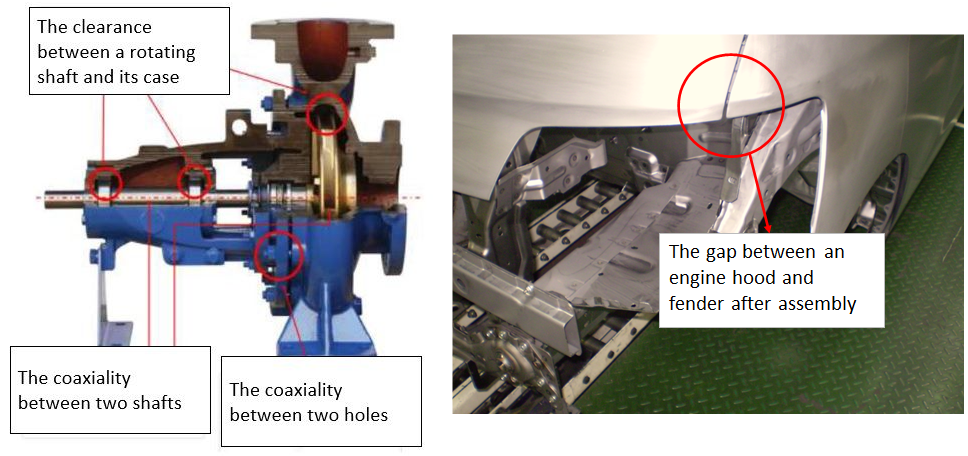
Assembly key characteristics (KCs)
The main goal of assembly processes is to achieve assembly key characteristics (KCs) within the KCs’ given tolerance. KCs are the dimension or size of assembly features or properties to achieve. Some examples of KCs (shown in figure 4) are the clearance between the rotor and stator of a centrifugal pump that should have values between $0-0.2 mm$ and the gap between the fender and engine hood of a car body that should be between $1mm$ and $2mm$.
In figure 4 left, the assembly of the centrifugal pump should satisfy the clearance requirement between the rotor and stator. Otherwise, there will be high friction, causing an early failure of the pump that is between the rotor and stator. In figure 4 right, the assembly of the car body is commonly more complex than the pump assembly. Because, the car body is constituted from metal sheets that are non-rigid components. The car body will be easily deformed during a handling or assembly process and cause the KCs of the car body cannot be achieved.
In conclusion, Assembly process is very important to realise functioning products and cannot be separated with tolerancing. In the past, before globalisation, many products are made from within a company. When there is no fit in assembly processes, operators will adjust manually the parts until the parts can be assembled (custom fit). This custom fit is not efficient, because, for example, this custom fit requires large numbers of manual labours and assembly time.
However, in the current globalisation era, part interchangeability is very important since many parts are made from different companies and from different countries. Tolerance specification, allocation and stack-up analysis play important roles to analyse and realise part interchangeability.
Tolerancing is also cannot be separated with dimensional, geometrical and surface metrology. Because, to verify whether, parts are within their tolerance, the part’s dimension and geometry should be verified by a measurement process.
We sell tutorials (containing PDF files, MATLAB scripts and CAD files) about 3D tolerance stack-up analysis based on statistical method (Monte-Carlo/MC Simulation).