Generating GPS L1 C/A pseudo-random noise (PRN) code with MATLAB and C/C++
In this post, C/A codes for GPS signals generation will be discussed. The C/A code implementation in MATLAB and C/C++ are presented as well.
In this post, C/A codes for GPS signals generation will be discussed. The C/A code implementation in MATLAB and C/C++ are presented as well.
Global positioning system (GPS), or in general global navigation satellite system (GNSS) is a type of spread spectrum communication [1,2]. With the spread spectrum communication, multiple-accesses of the GPS signals can be performed.
Spread spectrum communication is a type of communication where the baseband (narrow bandwidth) of transmitted signals are intentionally spread in frequency domain so that the signal has a wider bandwidth than the baseband bandwidth [3].
The main benefits of spread spectrum communication, for example, are multiple-access communication, natural and artificial interference resistance, secure communication and others [3].
GPS L1 C/A signal generation
The generation of GPS L1 C/A signals passes several steps including a spread spectrum modulation of the GPS baseband signals.
The spread spectrum modulation increases the bandwidth of the baseband signals. The spread spectrum is performed by modulating the narrow bandwidth signal with a pseudo-random noise (PRN) code that has a special correlation property.
Figure 1 below shows the steps to generate GPS L1 C/A signals. From figure 1, narrow bandwidth baseband signals (containing the navigation and almanac data) is modulated with a PRN code so that the spectrum of the baseband signal becomes significantly wide.
After the spread spectrum process of the baseband signals, the spread signals are modulated using binary phase-shift keying (BPSK) modulation method. Finally, the BPSK wide spectrum signals are then transmitted with a carrier signal at 1575.42 MHz (figure 1).
The PRN code has a special chip (referring to bit that does not represent any transmitted information) structure that has the specific correlation property: high auto-correlation and low cross-correlation.
The bit rate of GPS L1 signal is 50 bit per second (bps). With this 50 bps rate, the width of the spectrum (in frequency domain) is only ±50 Hz = 100 Hz.
Meanwhile, chip rate of the PRN of C/A code is 1.023 MHz (= Mega chip per second or Mcps). The 1.023 MHz is obtained because the number of chips of the PRN code is 1023/ms.
After modulating a PRN code with baseband signals, the spectrum (in frequency domain) width of the baseband signals becomes ±1.023 MHz = 2.046 MHz. This 2.046 MHz spectrum bandwidth is much higher than the original baseband bandwidth (before modulating with the PRN code) of only 100 Hz (figure 1).
(More detailed information regarding GPS signal generation and receiver processing can be read from this post).
PRN code generation of GPS L1 C/A signals
PRN code has essential roles in GPS signals. This PRN code is generated following a specific procedures proposed by Gold [4,5]. Hence, the PRN code is also known as Gold code.
Beside spread spectrum functionality of PRN code, this code also used to identify which satellite a received GPS signal comes from. That is, PRN code is also used to identify the satellite number (satellite id).
Each GPS satellite has a unique PRN code that is generated following the Gold procedure.
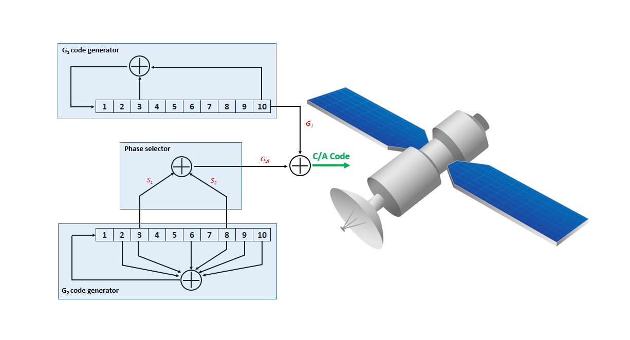
Figure 2 below shows the procedure to generate PRN C/A code for GPS L1. Note that “+” symbol in figure 2 is a modulo 2 sum operation.
In figure 2 above, the generator of C/A PRN code (gold code) consists of two register, called G1 and G2. Each shift register has 10 states.
From these two register G1 and G2 with 10 states each, a code sequence of 1023 length of code is generated. The G1 and G2 are modulo 2 summed together to generate the 1023 length of code.
Every 1023 period, both G1 and G2 are reset to have all 1 values so that the PRN code is repeated (start over again from the beginning).
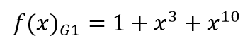
The polynomial feedback configuration of G1 is:
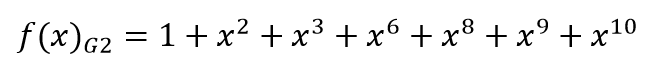
The polynomial feedback configuration of G2 is:
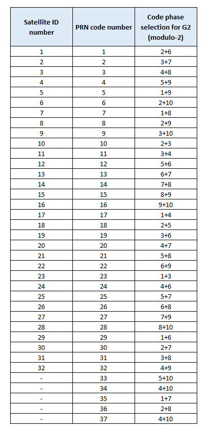
G1 directly supplied its register output. However, G2 supplies two of its states to another modulo-2 adder (phase selections) to produce the output of G2.
This special selection of states of the modulo-2 operation of the two output of G2 (before combined with the output of G1) is presented in table 1.
In table 1, the phase selection is presented to generate a unique C/A PRN code for each GPS satellite. Also, in table 1, only 32 PRN codes are used for satellites, the other 5 PRN codes are used for ground transmitters.
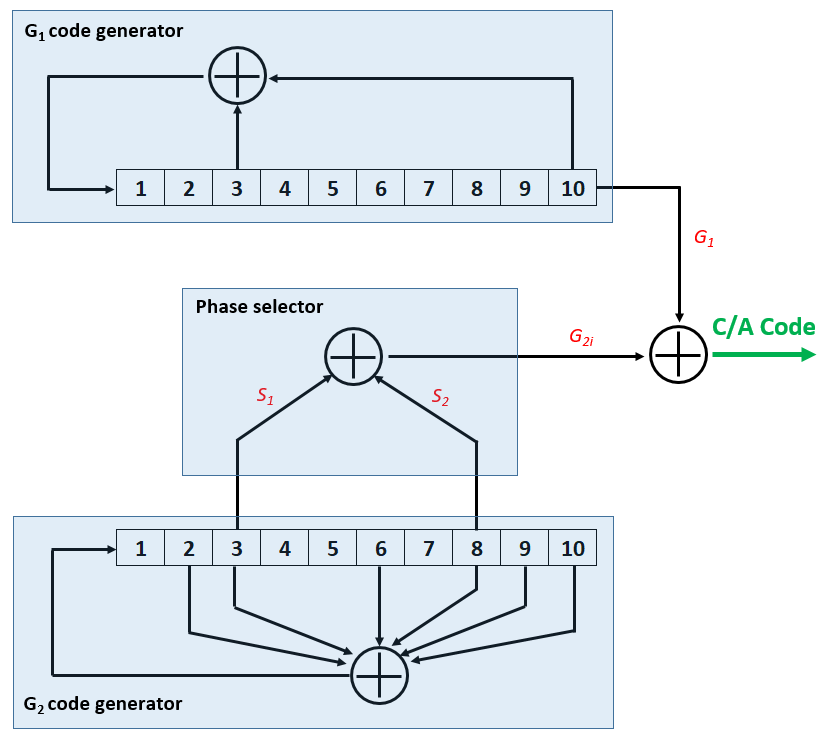
Shift register G1 and G2
In general, a shift register is a set of one bit storage (memory cells). The content of each register will shift one bit to the right when a clock pulse applied.
The output is the content of the last cell (the left most cell or register).
For G1, on each clock pulse, the taps at register position 3 and 10 are modulo-2 summed and the results is shifted to register position 1. And, the other registers are shifted one position to the right and finally the content in register positon 10 becomes the G1’s output.
For G2, on each clock pulse, the taps at register position 2, 3, 6, 7, 8, 9, 10 are modulo-2 summed and the results is shifted to register position 1. Similarly, all other register contents are shifted one bit to the right.
Then, depending on the phase selection shown in table 1, these two taps are then modulo-2 summed to be the G2’s output.
Finally, the output of G1 and G2 are modulo-2 summed together to produce the PRN code bit on each clock pulse.
MATLAB implementation of GPS C/A PRN code generation
The implementation of GPS L1 C/A PRN code in MATLAB is as follows:
function CACode = GpsCaCodePRN(sv)

    NUM_CODES = 37; %reserving 37 satellites
    SR_LEN = 20;

    CA_PERIOD = 1023; %the ca code length is 1023 chip/ms

    nchips = CA_PERIOD;

    % Initialise states of GPS_L1_CA_INIT_TABLE
    CA_INIT_STATES = [ ...
        [ 1, 1, 0, 0, 1, 0, 0, 0, 0, 0, 1, 1, 1, 0, 0, 1, 0, 1, 0, 0 ];
        [ 1, 1, 1, 0, 0, 1, 0, 0, 0, 0, 1, 1, 1, 0, 0, 0, 0, 0, 1, 1 ];
        [ 1, 1, 1, 1, 0, 0, 1, 0, 0, 0, 1, 1, 1, 0, 0, 0, 1, 0, 0, 0 ];
        [ 1, 1, 1, 1, 1, 0, 0, 1, 0, 0, 1, 1, 1, 0, 0, 0, 1, 1, 0, 1 ];
        [ 1, 0, 0, 1, 0, 1, 1, 0, 1, 1, 0, 0, 0, 1, 0, 0, 0, 1, 1, 0 ];
        [ 1, 1, 0, 0, 1, 0, 1, 1, 0, 1, 0, 0, 0, 1, 1, 0, 1, 0, 1, 0 ];
        [ 1, 0, 0, 1, 0, 1, 1, 0, 0, 1, 1, 1, 1, 1, 1, 1, 1, 1, 0, 1 ];
        [ 1, 1, 0, 0, 1, 0, 1, 1, 0, 0, 0, 1, 1, 0, 1, 1, 0, 1, 1, 1 ];
        [ 1, 1, 1, 0, 0, 1, 0, 1, 1, 0, 1, 0, 1, 0, 0, 1, 0, 0, 1, 0 ];
        [ 1, 1, 0, 1, 0, 0, 0, 1, 0, 0, 1, 0, 1, 0, 0, 0, 1, 0, 0, 1 ];
        [ 1, 1, 1, 0, 1, 0, 0, 0, 1, 0, 1, 1, 0, 0, 0, 0, 1, 1, 0, 1 ];
        [ 1, 1, 1, 1, 1, 0, 1, 0, 0, 0, 0, 1, 1, 0, 1, 0, 1, 1, 1, 0 ];
        [ 1, 1, 1, 1, 1, 1, 0, 1, 0, 0, 1, 0, 1, 0, 0, 1, 1, 1, 1, 0 ];
        [ 1, 1, 1, 1, 1, 1, 1, 0, 1, 0, 1, 1, 0, 0, 0, 0, 0, 1, 1, 0 ];
        [ 1, 1, 1, 1, 1, 1, 1, 1, 0, 1, 1, 1, 1, 1, 0, 0, 1, 0, 1, 0 ];
        [ 1, 1, 1, 1, 1, 1, 1, 1, 1, 0, 0, 1, 1, 0, 1, 0, 1, 1, 0, 0 ];
        [ 1, 0, 0, 1, 1, 0, 1, 1, 1, 0, 0, 0, 0, 0, 0, 0, 0, 1, 0, 0 ];
        [ 1, 1, 0, 0, 1, 1, 0, 1, 1, 1, 1, 0, 0, 1, 0, 0, 1, 0, 1, 1 ];
        [ 1, 1, 1, 0, 0, 1, 1, 0, 1, 1, 0, 1, 0, 1, 1, 0, 1, 1, 0, 0 ];
        [ 1, 1, 1, 1, 0, 0, 1, 1, 0, 1, 0, 0, 1, 1, 1, 1, 1, 1, 1, 1 ];
        [ 1, 1, 1, 1, 1, 0, 0, 1, 1, 0, 0, 0, 0, 0, 1, 1, 0, 1, 1, 0 ];
        [ 1, 1, 1, 1, 1, 1, 0, 0, 1, 1, 1, 0, 0, 1, 0, 1, 0, 0, 1, 0 ];
        [ 1, 0, 0, 0, 1, 1, 0, 0, 1, 1, 1, 1, 0, 1, 1, 1, 1, 0, 0, 0 ];
        [ 1, 1, 1, 1, 0, 0, 0, 1, 1, 0, 1, 0, 0, 0, 0, 1, 0, 0, 0, 0 ];
        [ 1, 1, 1, 1, 1, 0, 0, 0, 1, 1, 1, 1, 0, 1, 0, 0, 0, 0, 0, 1 ];
        [ 1, 1, 1, 1, 1, 1, 0, 0, 0, 1, 0, 1, 1, 1, 1, 0, 1, 0, 0, 1 ];
        [ 1, 1, 1, 1, 1, 1, 1, 0, 0, 0, 0, 0, 1, 0, 1, 1, 1, 1, 0, 1 ];
        [ 1, 1, 1, 1, 1, 1, 1, 1, 0, 0, 1, 0, 0, 0, 0, 1, 0, 1, 1, 1 ];
        [ 1, 0, 0, 1, 0, 1, 0, 1, 1, 1, 1, 0, 0, 1, 1, 0, 0, 1, 0, 1 ];
        [ 1, 1, 0, 0, 1, 0, 1, 0, 1, 1, 0, 1, 0, 1, 1, 1, 1, 0, 1, 1 ];
        [ 1, 1, 1, 0, 0, 1, 0, 1, 0, 1, 0, 0, 1, 1, 1, 1, 0, 1, 0, 0 ];
        [ 1, 1, 1, 1, 0, 0, 1, 0, 1, 0, 0, 0, 0, 0, 1, 1, 0, 0, 1, 1 ];
        [ 1, 1, 1, 1, 1, 0, 0, 1, 0, 1, 1, 0, 0, 1, 0, 1, 0, 0, 0, 0 ];
        [ 1, 1, 1, 1, 0, 0, 1, 0, 1, 1, 0, 1, 1, 1, 1, 0, 1, 1, 1, 0 ];
        [ 1, 0, 0, 1, 0, 1, 1, 1, 0, 0, 0, 0, 1, 0, 0, 0, 1, 0, 1, 0 ];
        [ 1, 1, 0, 0, 1, 0, 1, 1, 1, 0, 1, 0, 0, 0, 0, 0, 1, 1, 0, 0 ];
        [ 1, 1, 1, 1, 0, 0, 1, 0, 1, 1, 0, 1, 1, 1, 1, 0, 1, 1, 1, 0 ];
        ];

    FB_TAPS =[ 0 1 2 4 9 12 15 18]; %reciprocal poly for Fibonnacci Configuration

    LEN = nchips;
    nShifts = nchips - SR_LEN; % First SR_LEN bits are already in the shift reg

    %=======================CA code generation procedures=======================

    CACode = ones(length(sv),LEN);

    CACode(:,1:SR_LEN) = 1-2*CA_INIT_STATES(sv,:); %set the initialised state as the start code

    k = FB_TAPS;

    % shifts all the register
    for i = 1:1:nShifts
        k = k+1;
        CACode(:,i+SR_LEN) = prod(CACode(:,k),2);
    end

    CACode = (1-CACode)/2;

end
C/C++ implementation of GPS C/A PRN code generation
The implementation of GPS L1 C/A PRN code in C/C++ is as follows:
std::vector<int16_t> GpsCaCodePRN(int sv){

  int NUM_CODES = 37;
  int SR_LEN = 20;
  int CA_PERIOD = 1023;
  int nchips = CA_PERIOD;
  int LEN = nchips;
  std::vector<int16_t> code(LEN,1);
  int FB_TAPS[8] = {0, 1, 2, 4, 9, 12, 15, 18};
  int nShifts = nchips - SR_LEN; // First SR_LEN bits are already in the shift reg

  // Init states of genL1_CA_INIT_TABLE
  int CA_INIT_STATES[37][20] = {
    { 1, 1, 0, 0, 1, 0, 0, 0, 0, 0, 1, 1, 1, 0, 0, 1, 0, 1, 0, 0 },
    { 1, 1, 1, 0, 0, 1, 0, 0, 0, 0, 1, 1, 1, 0, 0, 0, 0, 0, 1, 1 },
    { 1, 1, 1, 1, 0, 0, 1, 0, 0, 0, 1, 1, 1, 0, 0, 0, 1, 0, 0, 0 },
    { 1, 1, 1, 1, 1, 0, 0, 1, 0, 0, 1, 1, 1, 0, 0, 0, 1, 1, 0, 1 },
    { 1, 0, 0, 1, 0, 1, 1, 0, 1, 1, 0, 0, 0, 1, 0, 0, 0, 1, 1, 0 },
    { 1, 1, 0, 0, 1, 0, 1, 1, 0, 1, 0, 0, 0, 1, 1, 0, 1, 0, 1, 0 },
    { 1, 0, 0, 1, 0, 1, 1, 0, 0, 1, 1, 1, 1, 1, 1, 1, 1, 1, 0, 1 },
    { 1, 1, 0, 0, 1, 0, 1, 1, 0, 0, 0, 1, 1, 0, 1, 1, 0, 1, 1, 1 },
    { 1, 1, 1, 0, 0, 1, 0, 1, 1, 0, 1, 0, 1, 0, 0, 1, 0, 0, 1, 0 },
    { 1, 1, 0, 1, 0, 0, 0, 1, 0, 0, 1, 0, 1, 0, 0, 0, 1, 0, 0, 1 },
    { 1, 1, 1, 0, 1, 0, 0, 0, 1, 0, 1, 1, 0, 0, 0, 0, 1, 1, 0, 1 },
    { 1, 1, 1, 1, 1, 0, 1, 0, 0, 0, 0, 1, 1, 0, 1, 0, 1, 1, 1, 0 },
    { 1, 1, 1, 1, 1, 1, 0, 1, 0, 0, 1, 0, 1, 0, 0, 1, 1, 1, 1, 0 },
    { 1, 1, 1, 1, 1, 1, 1, 0, 1, 0, 1, 1, 0, 0, 0, 0, 0, 1, 1, 0 },
    { 1, 1, 1, 1, 1, 1, 1, 1, 0, 1, 1, 1, 1, 1, 0, 0, 1, 0, 1, 0 },
    { 1, 1, 1, 1, 1, 1, 1, 1, 1, 0, 0, 1, 1, 0, 1, 0, 1, 1, 0, 0 },
    { 1, 0, 0, 1, 1, 0, 1, 1, 1, 0, 0, 0, 0, 0, 0, 0, 0, 1, 0, 0 },
    { 1, 1, 0, 0, 1, 1, 0, 1, 1, 1, 1, 0, 0, 1, 0, 0, 1, 0, 1, 1 },
    { 1, 1, 1, 0, 0, 1, 1, 0, 1, 1, 0, 1, 0, 1, 1, 0, 1, 1, 0, 0 },
    { 1, 1, 1, 1, 0, 0, 1, 1, 0, 1, 0, 0, 1, 1, 1, 1, 1, 1, 1, 1 },
    { 1, 1, 1, 1, 1, 0, 0, 1, 1, 0, 0, 0, 0, 0, 1, 1, 0, 1, 1, 0 },
    { 1, 1, 1, 1, 1, 1, 0, 0, 1, 1, 1, 0, 0, 1, 0, 1, 0, 0, 1, 0 },
    { 1, 0, 0, 0, 1, 1, 0, 0, 1, 1, 1, 1, 0, 1, 1, 1, 1, 0, 0, 0 },
    { 1, 1, 1, 1, 0, 0, 0, 1, 1, 0, 1, 0, 0, 0, 0, 1, 0, 0, 0, 0 },
    { 1, 1, 1, 1, 1, 0, 0, 0, 1, 1, 1, 1, 0, 1, 0, 0, 0, 0, 0, 1 },
    { 1, 1, 1, 1, 1, 1, 0, 0, 0, 1, 0, 1, 1, 1, 1, 0, 1, 0, 0, 1 },
    { 1, 1, 1, 1, 1, 1, 1, 0, 0, 0, 0, 0, 1, 0, 1, 1, 1, 1, 0, 1 },
    { 1, 1, 1, 1, 1, 1, 1, 1, 0, 0, 1, 0, 0, 0, 0, 1, 0, 1, 1, 1 },
    { 1, 0, 0, 1, 0, 1, 0, 1, 1, 1, 1, 0, 0, 1, 1, 0, 0, 1, 0, 1 },
    { 1, 1, 0, 0, 1, 0, 1, 0, 1, 1, 0, 1, 0, 1, 1, 1, 1, 0, 1, 1 },
    { 1, 1, 1, 0, 0, 1, 0, 1, 0, 1, 0, 0, 1, 1, 1, 1, 0, 1, 0, 0 },
    { 1, 1, 1, 1, 0, 0, 1, 0, 1, 0, 0, 0, 0, 0, 1, 1, 0, 0, 1, 1 },
    { 1, 1, 1, 1, 1, 0, 0, 1, 0, 1, 1, 0, 0, 1, 0, 1, 0, 0, 0, 0 },
    { 1, 0, 0, 1, 0, 1, 1, 1, 0, 0, 0, 0, 1, 0, 0, 0, 1, 0, 1, 0 },
    { 1, 1, 1, 1, 0, 0, 1, 0, 1, 1, 0, 1, 1, 1, 1, 0, 1, 1, 1, 0 },
    { 1, 1, 0, 0, 1, 0, 1, 1, 1, 0, 1, 0, 0, 0, 0, 0, 1, 1, 0, 0 },
    { 1, 1, 1, 1, 0, 0, 1, 0, 1, 1, 0, 1, 1, 1, 1, 0, 1, 1, 1, 0 }
  };

  if (sv < 1 || sv > NUM_CODES){
    std::cout << " ERROR: sv must be in the range 1 - " << NUM_CODES << '\n';
  }
  else {
    // Initialise: Put the init state at the start of the code
    for ( int i = 0; i < 20; i++ ){
      code[i] = 1-2*CA_INIT_STATES[sv-1][i];
  }

    int *k = FB_TAPS;

    // Shifts through all the registers
    for (int i = 0; i < nShifts; i++){
      int row_prod = (code[k[0]]*code[k[1]]*code[k[2]]*code[k[3]]*code[k[4]]*code[k[5]]*code[k[6]]*code[k[7]]);
      code[i+SR_LEN] = row_prod;
      for (int j = 0; j < 8; j++){
        k[j] = k[j] + 1;
      }
    }
  }

  for (int i = 0; i < LEN; i++){
    code[i] = (1-code[i])/2;
  }

  return code;

}
Conclusion
In this post, the procedure to generate C/A PRN code is explained and the implementation to generate the PRN code with both MATLAB and C/C++ programming languages are also presented.
The procedure to generate the PRN code follows the procedure initially proposed by Gold in [5].
PRN code is a special signal and is essential for GPS and other GNSS signals. Because, this code spread the spectrum of the baseband signals and is used to identify the satellite ID of received GPS signals.
There are a total of unique 37 PRN code already reserved to represent the 32 GPS satellites. The other 5 PRN codes are reserved for another use, for example, ground transmitters.
Reference
[1] P. Misra and P. Enge. 2006. “Global Positioning System: Signals, Measurement and Performance.” 2nd edition
[2] F. Van Diggelen. 2009. “A-GPS: Assisted GPS, GNSS, SBAS”
[3] J. K, Holmes 2007 Spread spectrum systems for GNSS and wireless communications (p. 76). Norwood, MA: Artech House.
[4] J. S. Subirana, J. M. J. Zorboza, M. Hernandez-Pajarez (2013). GNSS data processing. Volume 1: Fundamentals and algorithm. European Space Agency (ESA).
[5] Gold, Robert (1967). Optimal binary sequences for spread spectrum multiplexing. IEEE Transactions on Information Theory, 13(4):619–621.
We sell all the source files, EXE file, include and LIB files as well as documentation of ellipse fitting by using C/C++, Qt framework, Eigen and OpenCV libraries in this link.
We sell tutorials (containing PDF files, MATLAB scripts and CAD files) about 3D tolerance stack-up analysis based on statistical method (Monte-Carlo/MC Simulation).