Understanding fundamental assembly features: Mate and contact features
Assembly is the final step to make a product in its complete form. However, no matter how complex the geometry of a part is, the part’s assembly features are boiled down to two fundamental types: mate and contact features.
Assembly is the final step to make a product in its complete form. Only in the complete form, the product is ready to use (see Assembly and tolerancing). However, no matter how complex the geometry of a part is, the part’s assembly features are boiled down to two fundamental types: mate and contact features.
It is very important to know and understand what the assembly features are. With this understanding, we can systematically design an effective (accurate and precise) and efficient (low cost, flexible, and relatively short time) assembly process.
An assembly process should be based on systematic design processes and should not be merely based on experiences and intuitions.
Assembly features
A feature is defined as (see ASME Y14.5) the section of a component that has specific functions. Some examples of features on a part are slot faces, holes, pins, freeform surfaces with specific functions (not aesthetic functions).
Assembly feature is the feature on a component or part that has a specific functionality and involves in the assembly of this component with other components. There are two fundamental types of assembly feature:
- Mate feature is the feature to repeatedly (precisely) locate and orient two or more components to be assembled. This feature should be highly accurate than other non-mate features. Because, mate features directly determine the accuracy of the key characteristic (KC) of assemblies. Moreover, mate features provide relative motion constraints of parts during assembly.
- Contact feature is the feature to strengthen (provide force) two or more components to be assembled so that their assembly can still hold together. This assembly feature does not affect the KC of an assembly. This feature does not require the high level of accuracy (lower production cost) as mate features require because its main function is only to prevent components’ motion after the assembly.
A good part/product design should have both mate and contact features. For assembly and manufacturing efficiency, the mate and contact features should have similar shapes for all parts constituting the product to ease the assembly of the product.
Parts/products, having both mate and contact features, can be assembled easily. Because, the parts can precisely (repeatedly) position and orient themselves relative to the other parts, and constraint their relative motions during assembly without, or at least with minimal, the need of fixtures or other supporting equipment.
By the self-positioning and orienting as well as self-constraint among parts in an assembly, the assembly cost can be significantly reduced (due to, for examples, we do not need sensors, fixture, jig, clamping, robots and other special assembly machines).
Moreover, with correct mate and contact features design, the flexibility of an assembly process increases. Because, the assembly only requires minimal numbers (or none if possible) of fixtures. Also, the changeover (reconfiguration) time of the assembly for different product types can be minimised. Finally, the need for high-skill operators can be also minimised so that labour availabilities will be increased to do the assembly.
An effective and efficient assembly process should be considered starting from the design phase of a product. A good product design should be able to correctly use, integrate and optimise mate and contact features on parts that constitute the assembly.
Advantages of good assembly design of a product are:
- Minimise the use of fixtures
- Minimise the use of specialised machines
- Minimise the need of skilled operators
- Minimise changeover time among different types of products
- Minimise KC errors after assembly
- Minimise assembly time
- Minimise part interchange
- Increase assembly flexibility
- Increase assembly precision and accuracy
To clearly understand the concept of mate and contact features, three examples with different conditions are presented:
- Example 1: the assembly of two components that only has contact features (without mate feature) and has “under-constraint”
- Example 2: the assembly of two components that has both mate and contact features but has “over-constraint”
- Example 3: the assembly of two components that has both mate and contact features and has “kinematic-constraint”. This condition is an ideal situation of an assembly
The meaning of over-, under- and kinematic constraints are:
- Over-constraint: is a condition where the assembly of components (without any clamping, bolt and nut) have high residual-stress on the components after the assembly process. A common effect of over-constraint found in real assembly is part or component bending or deformation.
- Under-constraint: is a condition where the assembly of components (without any clamping, bolt and nut) still have relative motions among them.
- Kinematic-constraint: is a condition where the assembly of components (without any clamping, bolt and nut) does not have any relative motions among parts and does not have high residual stress after assembly.
Example 1
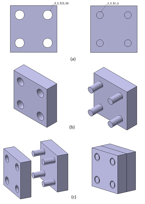
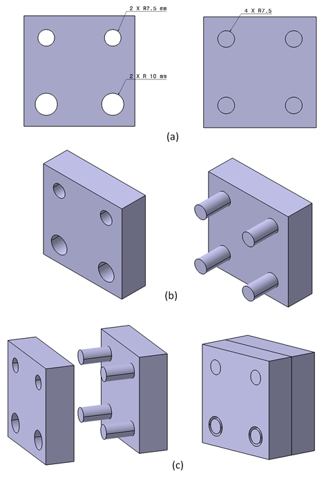
In this example, the assembly of two components that only has contact features is presented and are in “under-constraint” condition. Figure 1 shows the components of the assembly. In figure 1, one component has assembly features of four holes and the other component has four pins.
The main goal of the assembly is that the four pins on one of the components can enter the four holes of the other component so that the components can be joined together. Only the holes and pins affect the final assembly quality. The key characteristic (KC) of the assembly is that all of their side faces are at the same level with each other.
In figure 1a, the 2D view of the two components are shown. The diameter of the pins are 15 mm and the diameter of the holes are 20 mm. Note that we only talk in the design phase so that all dimensions are nominal and there is no tolerance considered. Figure 1b and 1c show the isometric view of the components and their assembly in perfect condition, respectively.
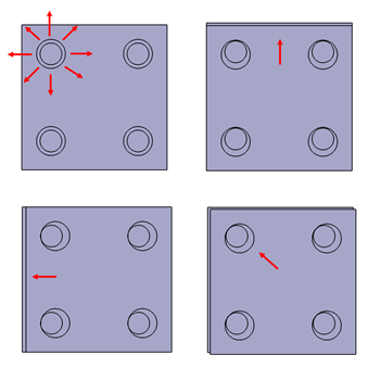
In this assembly state, since it does not have mate features, the components have relative planar motions, that are translation and rotation, between them. Figure 2 shows the relative planar motions between the components.
Because of the relative planar motions, when the contact features (the holes and pins) are joined together, the position from the assembly is not repeatable, that is when the components are disassembled and re-assembled again, their relative position after being joined will be different. This is because, the holes and pins, in this example, only act as contact features. Hence, the two components cannot be positioned and oriented accurately and precisely and there is no constraint for the relative planar motion during their assembly process.
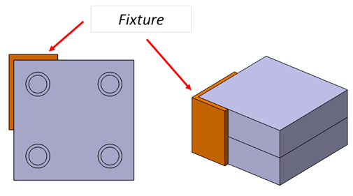
To solve the assembly problem in this example, a fixturing system, shown in figure 3, is required (of course with an additional cost) to provide relative movement constraints during the assembly. Also, the fixturing system enables the accurate positioning and orientation of the two components during the assembly. With the fixturing system, the assembly of the two components is repeatable, that is we will get approximately the same positioning and orientation of the components when we repeat the assembly process.
The design mistake in example 1 is that the components do not have mate features.
Example 2
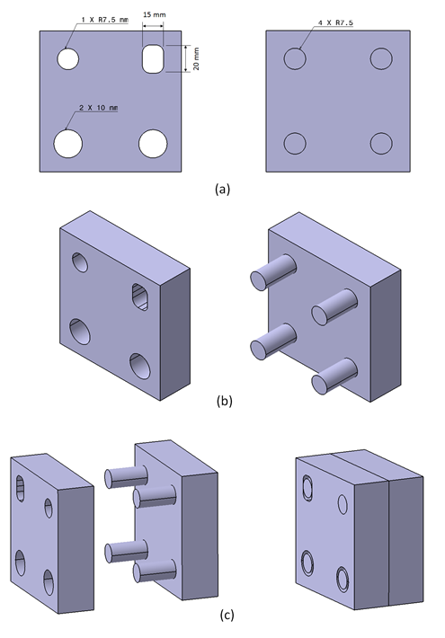
In this example, the assembly of two components that have both mate and contact features, but is in “over-constraint” condition is presented. Figure 4 shows the 2D view of the components and their assembly. The assembly features of the two components are two pins and holes as mate features and two pins and holes as contact features.
The mate features are the pins and holes that have 15mm diameter. The other two 15mm diameter pins and two 20 diameter holes are the contact features (note that we assume they are perfect so that there is no tolerance).
The mate features on the component provide motion constraint of the components when they are assembled. The contact features are only to strengthen the assembly by using, for example, bolt (represented by the pins) and nut.
Figure 4c shows their assembly process that does not require a fixture. Because, their mate features provide the constraint and enable accurate and precise positioning and orientation for the two components.
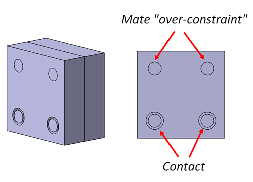
Figure 10 shows the detail of the assembly results and the over-constraint condition. The over-constraint condition occurs because there are more than one mate features that constraint the relative planar translation motion between the two components.
The negative effect of this over-constraint is that when there is a small deviation (and it will be in reality) on the diameter or location of the pins or holes, the assembly process will be difficult since the pins cannot enter the holes. This over-constraint condition causes excessive residual stresses on the parts after the assembly process.
The design mistake in example 2 is that the mate features provide more than one constraint for one direction.
Example 3
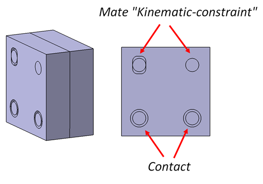
Example 3 presents the assembly of two components that have both mate and contact features. The mate features of the components have the right shape that provides exact number of constraints for both rotational and translational relative planar motions of the two components (during assembly). This assembly is in “kinematic-constraint” condition that is a desired assembly state.
Figure 6 shows the 2D view and isometric of the two components as well as the assembly process of the components. In Figure 6a, there are two mate features for each component:
- One hole or circular feature with diameter of 15mm. This mate feature constraints relative translational motion of the components.
- One slot with dimension of 15 mm wide and 20 mm height. This mate feature constraints relative rotational motion of the components.
The assembly process of the components does not require any fixtures. Because, the relative motion constraints during the assembly, and accurate positioning and orientation of the components have been provided by the mate features.
Figure 7 shows the detail of the shape of the mate features of the components. With the different shape of the mate features (the hole and slot), kinematic-constraint condition can be obtained. Because, each relative translational and rotational movement have exactly one constraint.
From the three examples above, it has been shown that with correct component designs, the assembly process of the components can be easy, accurate and have low assembly cost. The three examples above are the simplest illustration to explain assembly (mate and contact) features and their important role in assembly. In real conditions, the shape of components will be commonly complex, but their assembly features will be down to simple prismatic shapes (mostly), such as pin and hole.
To quantitively analyse over-, under- and kinematic constraints of assembly features, we can use screw theory. This theory provide methodology to quantitively analyse the relation between the assembly features of a part with the assembly feature of other parts and to evaluate the constraint conditions (over, under or kinematic).
Conclusion
Assembly is “the moment of truth” where a complete functional product can be obtained.
The main goal of assembly design is to have an assembly state of components that is in kinematic-constrained condition with minimal fixtures (reduce cost) and to have fast and easy assembly processes.
No matter how complex parts constitute an assembled product, their assembly features are boiled down into two fundamental types:
- Mate feature: is the feature to precisely locate and orient two or more components to be assembled and to provide relative motion constraints of parts during assembly. Mate features directly affect the key characteristic (KC) of assemblies.
- Contact feature: is the feature to strengthen two or more components to be assembled so that their assembly can still hold together, that is to prevent components’ motion after the assembly.
Products that do not have mate features will require fixturing systems in their assembly process. The fixturing system will increase the cost (especially to design and manufacture the fixture) and complexity of the assembly process.
So, we must correctly design the assembly of a product (do not based an assembly process only based on experience and intuition) since its design phase following a systematic way!
We sell tutorials (containing PDF files, MATLAB scripts and CAD files) about 3D tolerance stack-up analysis based on statistical method (Monte-Carlo/MC Simulation).