Evil waveform (EWF) in global navigation satellite system (GNSS) signal
In this post, we will discuss one of GNSS threats, that is evil waveform. Unlike jamming and spoofing, evil waveform is not a type of signal interference in GNSS signals. Instead, evil waveform is a faulty signal transmitted by a real GNSS satellite.

In this post, we will discuss one of GNSS threats, that is evil waveform. Unlike jamming and spoofing, evil waveform is not a type of signal interference in GNSS signals. Instead, evil waveform is a faulty signal transmitted by a real GNSS satellite.
The faulty signal is caused by the failure of pseudo-random number (PRN) and/or baseband signals in the GNSS satellite payload. The failure can be either from digital distortions or analog distortions or both digital and analog distortions.
Satellite payload is the signal processing steps from signal generation and modulation in digital domain until signal transmission with a transmission carrier in analog domain.
The most famous evil waveform incident was reported in 1993 on PRN 19 by [1]. This evil waveform caused position errors between 3 m and 8 mfor aviation differential global positioning system (GPS). For differential GPS, positioning errors of 3 m to 8 m are unacceptable, especially the critical purpose of a differential GPS is as a guidance system for airplane.
Hence, evil waveform (EWF) really causes a serious integrity issued of GNSS systems. EWF should be seriously considered as part of overall integrity assessment check lists.
READ MORE: GNSS spoofing: a fatal attack on GNSS system that is difficult to detect
- Global Positioning System: Signals, Measurements, and Performance - an excellent GPS and GNSS book for modelling
Evil waveform in GNSS: A brief introduction
The distortion on generated PRN code on GNSS signals creates EWF signal. The distortion can be from a delay in a chip rising or falling edge or the distortion of the chip pulse.
These distortions can occur at the digital domain where the PRN signals are generated or at the analog domain when the PRN is modulated by the carrier or even can occur at both digital and analog domain.
In addition, the distortions can be one type at a time or combination of several distortions.
There are various types of evil waveform, some of the most important types are [2]:
- Digital distortion: This EWF distortion is in the form of lag or lead in the falling edge of its baseband signals.
- Analog distortion: This EWF distortion impose amplitude modulations on the pulse shape of PRN signals.
- Combined (digital+analog) distortion: This EWF distortion has both lag or lead on the falling edge of the pulse and also has imposed amplitude modulations on its PRN pulse shape.
Figure 1 below shows the illustration of the EWF signals (adapted from [2]). In Figure 1, distortion on digital domain only cause a certain lag or lead at the falling edge of the signal pulse (baseband signal). Meanwhile, the anolog distortion introduces amplitude modulations on the PRN pulse shape.
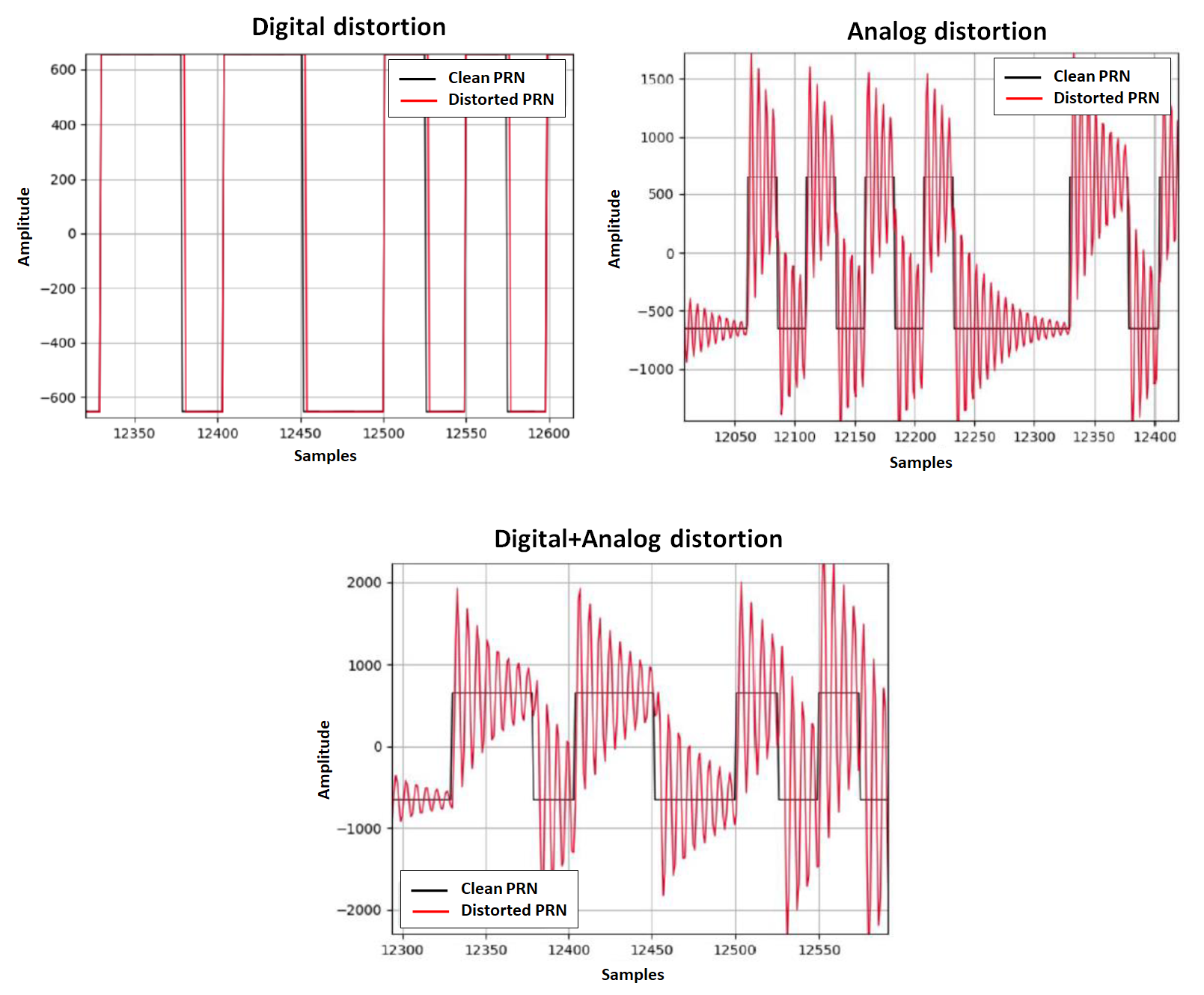
From figure 1 above, it can be observed that digital distortions cause the digital baseband signal to have a lag (in this case) at the falling edge with respect to the clean digital signal. Meanwhile, for analog distortion, the distortion is very clear as the amplitude of the signal becomes “ringing shape” instead of flat rectangular shape.
READ MORE: GNSS signal modelling considering channel impairments and spoofing interferences

Evil waveform detection
Some EWF detection methods have been proposed, and one of them is reported in [2,3]. In this proposed approach, signal quality metric (SQM) combined with statistical test detection (following Neyman-Pearson criterion) are proposed to detect EWF.
The main idea of the detection method is to utilise metrics calculated from multi-correlator output (in signal tracking processes) and compared the metrics (in term of their ratio) with respect to nominal pre-calculated values calculated from clean signals.
If the metrics comparisons have values above a threshold, then EWF detection alarm will be triggered. The determination of the threshold values is based on Neyman-Pearson hypothesis testing criteria. The criteria consider expected false alarm and false detection of the detection.
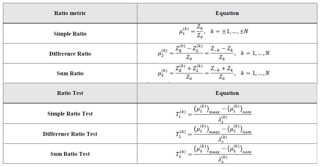
Figure 2 above shows the list of the SQM metrics applied to multi-correlator early-late-prompt values and the ratio tests to detect EWF signals.
From figure 2, the there are three metrics: simple ratio, difference ratio and sum ratio. The index $E,L,O$ are for early, late and prompt correlator values, respectively.
Each metric has its ratio test. Hence, the ratio tests are simple ratio test, difference ratio test and sum ratio test, respectively. From the ratio test, the variables $T$ and $\lambda$ are the threshold value and test parameters, respectively. The $\lambda$ variable is determined based on Neyman-Pearson criteria.
READ MORE: The difference between C/N0 and SNR in GNSS signal processing

Conclusion
EWF definition and its impact on the integrity of GNSS systems have been discussed in this post. EWF is not a type of signal interference such as jamming and spoofing. In fact, EWF is a genuine GNSS signal but with some imperfections or faulty elements on its PRN section.
Failures in GNSS satellite payload create distortions in either digital domain or analog domain or both digital and analog. These distortions then produce EWF signals.
EWF signal will seriously reduce the accuracy of calculated positions from the GNSS EWF signal. That is why, EWF should be considered in all integrity assessments of GNSS receivers.
Current EWF mitigations are, for example, by using statistical quality monitoring on the early-late-prompt correlators or multi-correlators from GNSS signal tracking process. Detections of EWF are then by using statistical test by specifying a threshold with respect to an expected false alarm rate.
References
[1] Edgar, C., Czopek, F. and Barker, B., 1999, September. A co-operative anomaly resolution on PRN-19. In Proceedings of the 12th International Technical Meeting of the Satellite Division of The Institute of Navigation (ION GPS 1999) (pp. 2269-2268).
[2] Negrinho, A., Fernandes, P., Boto, P., Nunes, F. and Sousa, F., 2021, September. Evil waveforms detection solutions for autonomous navigation integrity. In Proceedings of the 34th International Technical Meeting of the Satellite Division of The Institute of Navigation (ION GNSS+ 2021) (pp. 4097-4115).
[3] Negrinho, A., Boto, P., Fernandes, P., Mendonça, V., Nunes, F. and Sousa, F., 2022, September. Signal Quality Monitoring Aspects in GNSS Signals Affected by Evil Waveforms. In Proceedings of the 35th International Technical Meeting of the Satellite Division of The Institute of Navigation (ION GNSS+ 2022) (pp. 3947-3958).
You may find some interesting items by shopping here.