Fastener design and projected tolerance zone
In this post, we will discuss two main types of mechanical fastener: floating and fixed fasteners as well as projected tolerance zone to control the geometrical variations of fixed fasteners.
In this post, we will discuss two main types of mechanical fastener: floating and fixed fasteners as well as projected tolerance zone to control the geometrical variations of fixed fasteners.
Fasteners are very important in any assembled products. Fasteners join two mating parts together to form an assembly or a sub-assembly of a whole product.
That is fasteners join two parts. Although simple, fasteners are instrumental in any mechanical assemblies and we need to carefully tolerance fasteners and their holes to join/mate two parts correctly.
Fasteners have many forms, for example, bolts and nuts, screws, rivets, nails and other components joining two or more parts. Fasteners are the most common machined parts in product manufacturing and assembly.
At the end of this blog, readers will understand the main differences of fixed and floating fasteners (for making design decisions) as well as how to tolerance fasteners.
Let’s go into the discussion!
READ MORE: Inspection of geometric tolerances: GO and NOGO gaging system
Fastener design: fixed and floating fastener
There are two main types of fasteners: fixed and floating fasteners. Each type has different characteristics.
Floating fasteners usually have a function to join and hold (as contact feature) parts together as an assembly.
Fixed fasteners usually have a function to precisely locate (as mating feature) a part with respect to its mating part in an assembly. Hence, the tolerance requirement is more stringent than floating fastener.
Fixed fastener
The basic construction of fixed fasteners is that one part has clearance holes and the other mating part has threaded holes. The threaded holes fix the fasteners at one position.
Fixed fasteners are to precisely locate a part with respect to its mating part.
Some examples of fixed fasteners are a bolt passing through a clearance hole in one part and fixed at the other part at a threaded hole. The bolt may or may not protrude from the threaded hole.
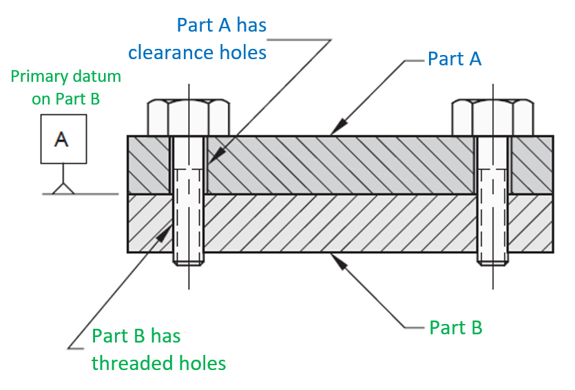
Figure 1 below shows an example of fixed fasteners. From figure 1, the characteristic of fixed fasteners can be summarised as follows:
- External features (pins, or studs or bolt) pass through internal features (clearance hole) and fixed at one part (the mating part).
- The fixing method can be, for example, pressing a pin, welding studs or fixing into threaded holes.
- The fastener and the threaded hole are coaxial each other.
- The threaded hole locate (mating feature) the fasteners.
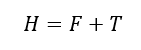
To calculate the diameter of clearance holes in fixed fastener assembly (as illustrated in figure 1), we can use the fixed fastener formula:

Where:
$H$ is the minimum clearance hole diameter (at MMC).
$F$ is the maximum fastener diameter (at MMC).
$T_{1}$ is the position tolerance of the clearance hole (part A) (at MMC).
$T_{2}$ is the position tolerance of the threaded hole (part B) (at MMC).
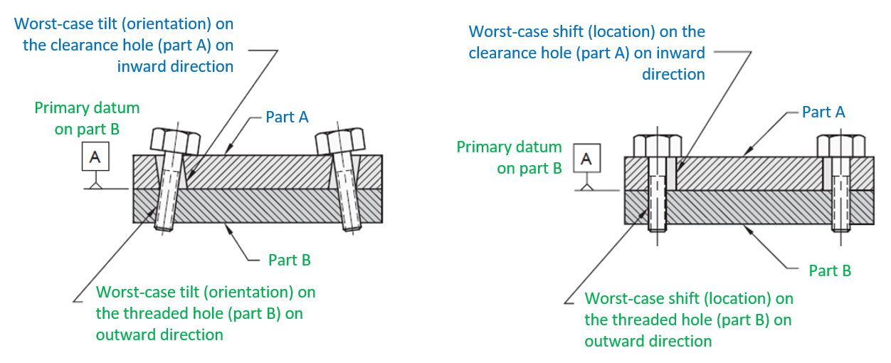
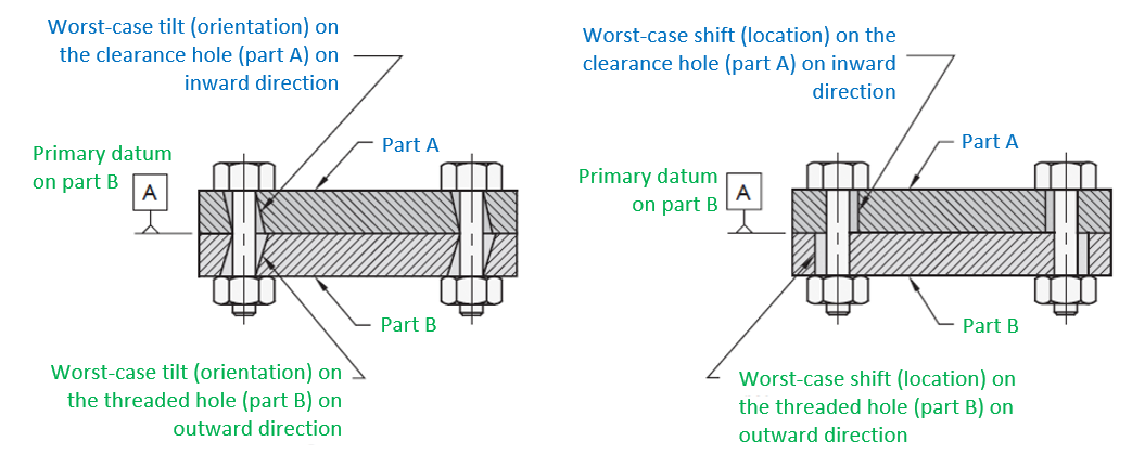
Figure 2 below presents possible worst-case conditions for fixed fasteners, which are both the clearance hole and threaded hole have the worst-case tilt at opposite directions or both the clearance hole and threaded hole have the worst-case shift at opposite directions.
From figure 2, any tilt deviations on threaded holes will also affect the orientation of the fasteners.
Floating fastener
Floating fasteners usually have a relaxed tolerance compared to fixed fastener due to the main aims of floating fastener is to provide contact force for joining two or more parts together.
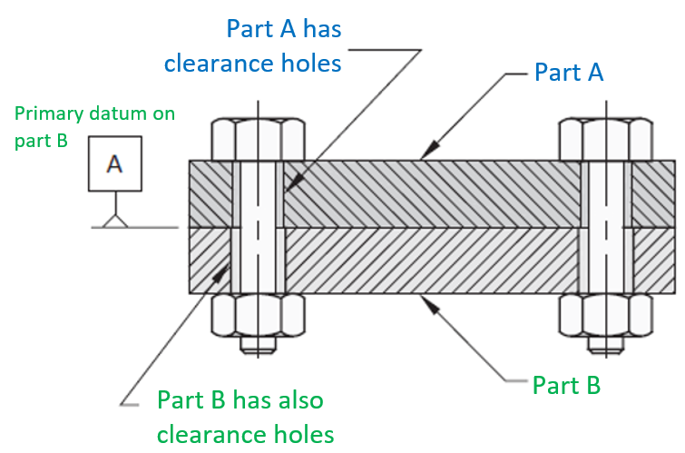
Some examples of floating fasteners are bolts pass through clearance holes on two or more parts. Usually, the floating fastener uses hex nuts to terminate the bolts and to provide required contact forces.
Figure 3 below shows the illustration for floating fasteners. In this figure we can see that both parts (plates) have clearance holes. The bolts are terminated by hex nuts to give contact force to join/hold the two parts.
The characteristics of floating fasteners are as follows:
- Internal features (holes) in both parts must clear external features (pin or studs).
- Commonly in the form of bolt and nut joining.
- Clearance holes do not locate the fastener.
- Fasteners are free to move (float) within clearance holes.
To calculate the diameter of clearance holes in floating fastener assembly (as illustrated in figure 3), we can use the floating fastener formula:
Where:
H is the minimum clearance hole diameter (at MMC).
F is the maximum diameter of the fastener (at MMC).
T is the position tolerance of the clearance hole at considered part (at MMC).
Figure 4 below illustrates possible worst-case conditions for floating fasteners, which are both the clearance hole and threaded hole have the worst-case tilt at opposite directions or both the clearance hole and threaded hole have the worst-case shift at opposite directions.
Unlike on fixed fasteners, for floating fasteners, the tilt deviations on clearance holes on both parts may not necessarily affect the orientation or tilt of the fasteners.
One important thing to consider is that assembly sequences (including gravity effect on resting vertical parts) affect the functionality or assembly characteristic of floating fasteners!
This means although the clearance holes on both mating parts satisfy their geometric tolerances, with a wrong assembly sequence, fasteners may not go through the holes.
In addition, the sequence of part assemblies, especially in vertical positions, the gravity effect will shift assembled parts downward and may cause fasteners cannot go through their designed mating holes although the holes satisfy their geometric tolerances.
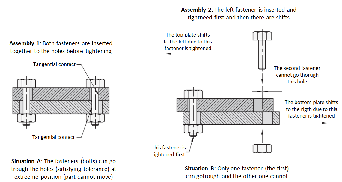
Figure 5 below shows the illustration how assembly sequences affect whether fasteners can go through the clearance holes of mating parts or not.
From figure 5, there are two types of assembly sequences.
On assembly sequence 1 (figure 5 left), both fasteners are firstly inserted into the clearance holes of the parts. After that, the nuts of the bolts are tightened.
The results of this assembly sequence 1 is the bolts can go through the clearance holes when the holes satisfy their geometric tolerances. At extreme deviation, the bolts just fit to the holes and cannot move.
On assembly sequence 2 (figure 5 right), the first fastener is inserted first and tightened. After that, the second fastener is inserted.
However, since there is a large shift, due to hole geometrical deviation from nominal, when inserting the first fastener, we cannot insert the second fasteners to the holes since the shift cause the clearance holes for the second fastener to be too small for the second fastener to go through.
The results from assembly sequence 2 is the second bolts cannot go through the holes even though the holes satisfy their geometrical tolerances!
Hence, we need to be careful when we assemble floating fasteners on mating parts.
READ MORE: Understanding fundamental assembly features: Mate and contact features
Projected tolerance zone
The projected tolerance zone is a type of geometrical tolerance which indicates the tolerance zone of a feature (threaded hole) is to be established above the surface extents of the feature (top of the threaded hole) with respect to the feature’s datum surface.
The main aim is to assure a fixed fastener will still go through the clearance hole of a mating part during assembly when the mating part satisfies its geometrical tolerance (location and orientation of clearance hole in which the fastener will be assembled into).
The fixed fastener can still go through the hole regardless of how thick the mating part is and the orientation the assembled fixed fastener.
That is, projected tolerance zone is designed for fixed fastener.
There are at least two reasons of why projected tolerance zone is for fixed fastener:
- Floating fastener is affected by assembly sequences. Meaning, when clearance holes of mating parts satisfy their geometrical tolerance, there is no guarantee that fasteners can go through the holes due to the dependency on how the fasteners are assembled together.
- Unlike in the case of fixed fastener, the tilt variations on threaded holes will also affect the orientation of the fasteners. The tilted fasteners may cause the interference with wall of the clearance holes of the parts.
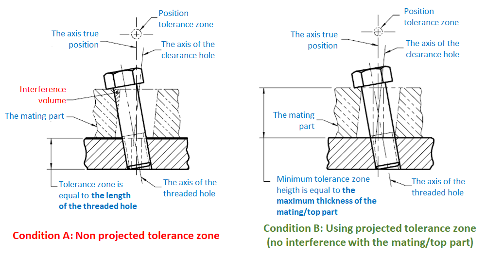
Figure 6 below shows the comparison between a fixed fastener without and with projected tolerance zone.
In figure 6 left, the fastener of a mating part assembly touches the side wall of the clearance hole of the top part.
The clearance hole and the threaded hole satisfy their position tolerance. The length of the position tolerance zone is equal to the length of the thickness of the bottom part.
Since there is a tilt on the treaded hole, the fastener is also tilted, and some portion of the fastener interfere with the wall of the clearance hole.
In figure 6 right, the same mating part assembly with figure 6 left with the same dimension and position tolerance.
However, in this case, the projected tolerance zone on the threaded hole is applied. The projected tolerance zone set the tolerance zone of the geometric tolerance of the threaded hole to be shifted up from the bottom part surface with the length equal to the thickness of the top part.
Hence, in this condition, although the fastener is tilted, the fastener does not touch the wall of the clearance hole.
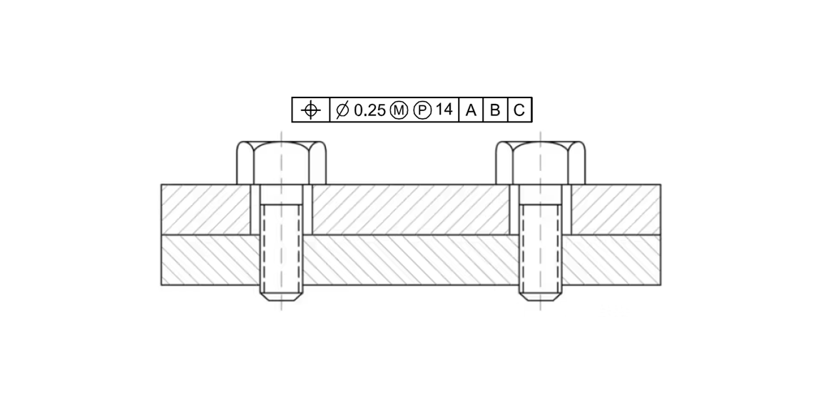
There are two styles of implementing projected tolerance zone on GD&T symbols.
Figure 7 below shows the type 1 projected tolerance zone application on GD&T symbols. In this type, the projected tolerance zone is applied on the tolerance frame by adding “circled P” and the length of the tolerance zone on top of feature surface.
In this example, the length of the tolerance zone is 14 with respect to the top surface of the feature with the projected tolerance zone symbol.
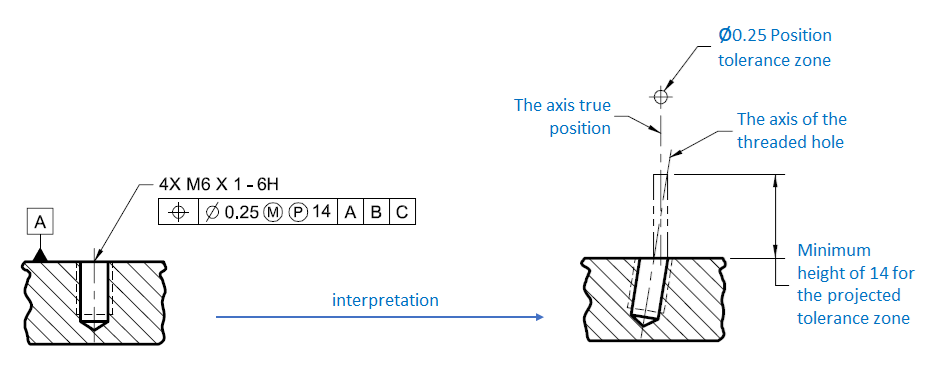
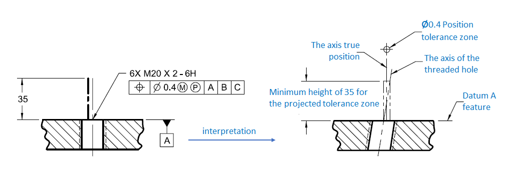
Figure 8 below shows the type 2 projected tolerance zone application on GD&T symbols. In this way, the projected tolerance zone is applied by adding a “circled P” symbol on the tolerance frame.
The length of the projected tolerance zone on top of feature surface is represented by an axis with the height dimension, in this example is 35, as the length of the projected tolerance zone.
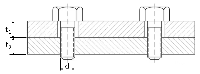
Finally, there are two rule of thumbs we need to follow to apply projected tolerance zone on fix fastener assemblies.
The two rules of thumb when applying the projected tolerance zone symbol on fixed fasteners are as follows:
- First: A mating part with a clearance hole has a thickness greater than the diameter of the bolt or pin being used ($t_{1}>d$).
- Second: The thickness of the mating part (clearance hole) is greater than the thickness of the bottom part with threaded or tapped hole ($t_{1}>t_{2}$).
Figure 9 below shows the illustration of the two rules of thump for projected tolerance zone on fix fasteners. In figure 9, $t_{1}$ is the thickness of the top part with clearance hole, $t_{2}$ is the thickness of the bottom part with threaded hole and $d$ is the fastener (bolt) diameter.
READ MORE: How BMW reduces their assembly cost by optimising assembly features and fixturing constraints
Conclusion
This post has discussed the two main types of fasteners: fixed and floating fasteners. These fasteners have different aims and characteristics with respect to assembling mating parts.
Fixed fastener is affected by the tilt of the threaded hole. Meanwhile, floating fastener is affected by assembly sequences.
Both fixed and floating fastener have different formulas to determine the size of the diameter for clearance holes. These two formulas have also been presented in this post.
Finally, for fixed fastener, we have also discussed about the projected tolerance zone applications. This projected tolerance zone is specifically designed to guarantee a fix fastener will not have interference with the side wall of clearance holes on its mating part.
Reference
[1] Fischer, B.R., 2004. Mechanical tolerance stackup and analysis. CRC Press.
[2] ASME Y14.5-2009. Dimensioning and Tolerancing.
You may find some interesting items by shopping here.