How BMW reduces their assembly cost by optimising assembly features and fixturing constraints
BMW reduces their total assembly cost by significantly reducing, if not completely eliminating, fixtures for assembly.

BMW reduces their total assembly cost by significantly reducing, if not completely eliminating, fixtures for assembly. Their way is by good designs of assembly features of their sheet-metal body part.
We will discuss and show how BMW optimises their assembly feature design and significantly reduces their fixtures in their car body assembly line.
The technical basisof this post can be read from these posts: assembly features, fixturing constraints and 3D tolerance analysis as well as a practical working example of 3D tolerance analysis.
This post is derived from a published paper by researchers at BMW and TU Munich. The title of the paper is “Tolerance analysis of compliant, feature-based sheet metal structures for fixtureless assembly”.
For more papers regarding assembly design and analysis for a measuring instrument design, readers can read our paper “Development of a compact focus variation microscopy sensor for on-machine surface topography measurement”.
Let us go to this very interesting discussion!
The role of fixtures in assembly process
Fixturing system is an essential system in assembly process of products.
Because, fixturing system is used to deterministically (precisely) position and orienting a part with respect to its counterpart to be assembled together.
In addition, fixturing system is also used to keep the position of a part when the part is given forces, such as, the one from spot welding processes in car body assemblies.
Especially for sheet-metal part assemblies, constituting car body assemblies, fixturing system is even more important and complex to design and implement. Sheet-metal parts are not rigid and has compliances that add difficulties in their assembly processes.
The compliances of sheet-metal parts cause the parts will be deformed by its own weight or during handling and will have spring-back effects when forces given to the part, for example from clamping, are release.
Figure 1 shows the conventional sequence of sheet-metal assemblies. In figure 1, the fixturing system contains clamping, to hold the sheet-metal parts to not moving when there are external forces from spot welding machines, and locators, to deterministically and precisely position and orienting the parts to their counterpart parts for assembly.
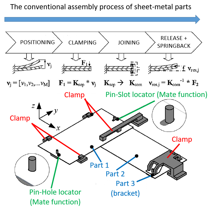
In figure 1 above, the common conventional assembly process for sheet-metal parts are:
- Positioning a part with respect to its mating part with fixture locators
- Clamping the parts so that they do not move during the assembly process (for example from spot welding machines and operator handling and adjustments)
- Joining the parts with, for example, spot welding machines or riveting processes
- Releasing, followed by “spring-back” effects from compliance parts, the sheet-metal parts from the fixturing system after being assembled
In figure 1 above, there is a slot hole that has a function to provide a small degree-of-freedom movement to fine adjust the sheet-metal parts without giving additional or unwanted forces and residual stresses to the parts so that the part to achieve its final position. In addition, the slot hole is used to provide compensations from the geometric errors of the sheet-metal parts.
(You can read this post about assembly feature designs to understand the function of slot hole in assembly).
Fixturing systems add costs to the total assembly cost. Not only adding costs, fixturing systems also add the complexity of the assembly and reduce the flexibility to change over or re-layout the setup of assemblies.
Ideally, fixturing system should be minimised in an assembly process without degrading the quality of assembled products.
Fixtureless assembly
The use of fixtures in assembly can be significantly reduced, if not completely eliminated, to lower the assembly cost and increase the agility and flexibility of an assembly setup.
This fixturing reduction can be performed if we can correctly and robustly design the assembly feature of parts.
A good part design (and its assembly design) is a design where assembly features have a correct mate and contact features (please see this post for more details).
With the presence of mate and contact features, a part can deterministically and precisely locate (position + orienting) itself with respect to its counterpart in an assembly.
Very common, an assembly that requires many fixture usually does not have mate features and only have contact features on their components.
BMW case study: Comparison between conventional fixturing and fixtureless assembly
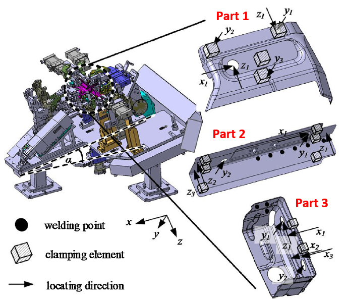
The case study of a BMW assembly process uses three sheet-metal parts. Figure 2 below shows the parts and their assembly for the case study.
From figure 2, the three parts have sizes ranging from relatively small, mid to large sizes. In figure 2a, the dimension and geometric tolerances of the parts are shown.

In the next section, from this case study, we will discuss two types of assembly processes: with conventional fixturing system and with fixtureless system.
Assembly with conventional fixturing system
The first assembly process is by using a conventional fixturing system. Figure 3 shows the conventional fixturing system solutions to assemble the three parts into an assembled part.
In figure 3, the need of the conventional fixturing system is because the three sheet-metal parts do not have enough mate features on them.
Since there is not enough mate features on the parts, the parts cannot self-position themselves and need the “help” from the fixturing system.
However, even though this conventional fixturing system works, the fixturing system is costly and complicated. The complexity of the fixture causes the assembly system to be inflexible and difficult to change over or re-layout (low agility).
Assembly with fixtureless system
The fundamental idea of fixtureless assembly is that the assembly relies on inherent mate and fastening features on sheet-metal parts (in this case study) or any general parts (in general cases).
Those mate and fastening features are the ones that ensure the deterministic and precise positioning and orientation of parts.
Since fixtureless assembly is based on part features, another name for fixtureless assembly is that feature-based fixturing assembly.
Figure 4 top shows various shapes of mate and fastening features that can be implemented to sheet-metal parts.
In figure 4 top, for positioning or locator function, a circular pin and hole or slot hole can be used with different degree of freedom limitations (depending on the function of the features).
For both positioning or locator and clamping functions, a circular pin and slot collar or circular collar shape can be used.
Figure 4 bottom shows two illustrations between a conventional assembly requiring fixtures and fxtureless assembly based on part features.
In figure 4 bottom, we can observe that common hole features are used on the part so that a pin from fixtures is used to locate the two mating parts together. Meanwhile, the fixtureless assembly has parts with special shapes on the assembly feature to have inherent locating functions for the two mating parts.

The fixtureless assembly system in this case study only requires one fixture to attach part 1 to a base. Other parts: part 2 and part 3 can be joined later on without any fixtures and only depend on the assembly feature of the parts.
Figure 5 shows the assembly sequences of the fixtureless assembly for the sheet metal parts in the case study.

From figure 5 above, we can observe that the fixtureless assembly becomes much simpler compared to the assembly with fixtures. This simple assembly process significantly reduces cost and increase assembly flexibility and agility.
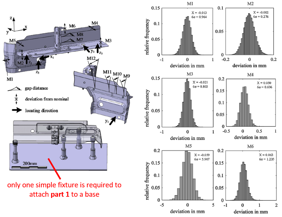
Only one simple fixture is used for this fixtureless assembly that is to attach part 1 to a base. Figure 6 left below shows the only simple fixture required by the fixtureless assembly. Compared to the conventional fixturing system shown in figure 3, this simple assembly setup with only one simple fixture is much cheaper and more flexible to set up.
3D tolerance analysis of the BMW fixtureless assembly
Another advantage of fixtureless assembly is that the total accumulated variation of assembly key characteristics (KC) is lower than the total variation from assembly with fixtures.
The reason of having low total assembly variation in fixtureless assembly is that the number of variation sources coming from fixture variations can be significantly reduced, if not completely eliminated.
In this case study, 3D tolerance analysis method is applied to estimate the total stacked-up or accumulated assembly variations on the assembly KCs that are gaps between two sheet-metals.
Figure 6 below presents the results of the 3D tolerance analysis. From figure 6, by using the tolerance analysis, the variation of the gaps can be estimated before the assembly is performed. From figure 6, with fixtureless assembly, small gap variations on M1-M6 can be obtained on the final assembled part.
Conclusion
The case study of a fixtureless assembly process from a BMW car body sheet metal parts is presented in this post.
This case study shows how important the understanding of GD&T, tolerance analysis and assembly features: mate and contact are.
The comparison between a conventional assembly process requiring fixtures and the fixtureless assembly is presented. The fixtureless assembly process can significantly reduce the total assembly cost and total gap variations between sheet metal parts.
Reference
[1] Schlather, F., Hoesl, V., Oefele, F. and Zaeh, M.F., 2018. Tolerance analysis of compliant, feature-based sheet metal structures for fixtureless assembly. Journal of manufacturing Systems, 49, pp.25-35.
Get the tutorial and working examples on 3D tolerance stack-up analysis based on statistical method (Monte-Carlo/MC Simulation). The tutorial contains PDF files, MATLAB scripts and CAD files.
You may find some interesting items by shopping here.