Understanding fixturing constraints: locator, clamping, support and guide
Fixturing system has a very important role in assembly processes. Despite the complexity of fixturing systems, there are four main roles that fixturing systems should have. The four roles are locating, clamping, supporting and guiding parts during assembly processes.
Fixturing system has a very important role in assembly processes. Despite the complexity of fixturing systems, there are four main roles that fixturing systems should have. The four roles are locating, clamping, supporting and guiding parts during assembly processes.
The required number and shape complexity of fixtures directly add up to the total cost of an assembly processes. Hence, designing a fixturing system for assembly is important and should be correctly done!
In this post, the concept of fixturing system will be explained with examples from simple to complex fixtures.
Fixturing system
Most assembly (and manufacturing) processes require fixturing systems. Because, most real products are constituted from many parts with complex geometry and have complex assembly sequences. These parts’ complex geometry and assembly sequences cause difficulty (if not impossible) to design the mate and contact features of the parts to achieve kinematic-constraints without any fixtures during their assembly processes.
Fixturing system is a system that is used to hold, support and construct interfaces between a component and relative to other components or the end-effector of a robot (for assembly and measurement process) or construct interfaces between a component and relative to a tool (machining process).
Fixturing system is very common to be found in assembly, machining and measurement processes. For measurement process, fixturing system is very common to be used for measurements with coordinate measuring machines (CMMs).
The fundamental elements of a fixturing system are:
- Locator: to accurately and precisely position and orient a component on Euclidean plane and to constraint all six degree-of-freedom (three translation x,y,z and three rotation along x-axis, y-axis and z-axes) relative motions of the component. With locators, a component can be deterministically (repeatedly) placed. Meaning, when the component is taken from and put back to its fixture locator, the component will be approximately at the same position (and orientation). The ideal locator rule is the “3-2-1 rule” that is explained in a later section.
- Clamping: to hold a component or workpiece so that it still firms on its position (during an assembly or machining process) when it excerpts external forces. Clamping mechanism uses friction forces between a workpiece and its clamp. In practice, a clamp will give a force with direction opposite to its locator force direction.
Meanwhile, additional elements of a fixturing system are:
- Support: to minimise deformations of a workpiece during an assembly or machining process due to, for example, the gravity force from the workpiece’s mass.
- Guide (jig): to help an actuator, for examples a drilling tool or a shaft or pin on a part, so that the actuator can achieve a desired position during an assembly or machining process. In other words, a guide (jig) is a fixturing system that interacts with other actuators. The other name of guide is jig. Jig is very common to be found, for example, in a drilling process, to get a precise drilling location and in a car body assembly to join panels.
Benefits obtained from fixturing system are:
- Increase the quality (accuracy and precision of the assembly key characteristics) of assembled products
- Reduce the total cost of an assembly process (and then the total production cost) in the form of helping assembly operators to quickly position parts to be assembled (speed up an assembly process)
However, a good product design should consider minimising required number of fixtures. Because, making fixtures will add cost to the total production cost of a product. So, there will be trade-off between the cost reduction provided by fixtures and the cost addition to make the fixtures.
The cost of fixturing system of a product can be 20% of the total assembly cost of the product
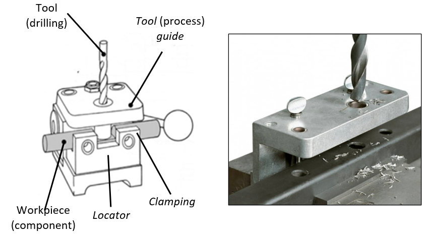
An example (by using 3D computer model) to clarify the functions of fixturing system is shown in figure 1. In figure 1, an ideal fixturing system that follows the “3-2-1 principle” and consists of locator, locator-support (base) and clamping is presented.
The workpiece in figure 1 is a rectangular block. It is worth to note that in a real situation, fixturing systems used will be far different from this simple example. Because, in real situation, products to be assembled have complex shapes.
In figure 1, there are three locator-supports (base) for constraining and supporting the workpiece, two locators on the long side, one locator on the short side and three clamping that give force in opposite direction of the locators’ force direction. It is important to have a balance force to minimise moment exerted on the workpiece because the moment tends to create rotational movements and cause bending (deformation) on the workpiece.
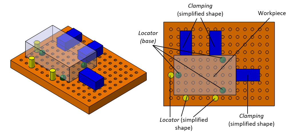
The functions of three locator-supports (base) in figure 1 (in green) are to constraint the movement in vertical direction due to the workpiece gravity force. The two locators on the long side of the workpiece are to constraint the motion in x-direction. Meanwhile, one locator on the short side of the workpiece is to constraint motion y-direction.
There are three clamping that apply force to push the workpiece toward its locators so that the workpiece can stay firm on its position. The clamping force axes are coincident with the one on its locators to provide balance force and minimise moment bending.
Six degree-of-freedom and “3-2-1 principle”
A part without any constraints will have six degree-of-freedom (6-DoF) movement in space, that are three translation in x,y,zdirections and three rotations along x-, y- and z-axes. The axes are centred on the part centre of mass.
To prevent motions during an assembly, machining or measurement processes, the 6-Dof motion of the part should be limited (constrained). In ideal condition, the constraint mechanism of the part should follow “3-2-1 principle”.
A fixturing system satisfying the “3-2-1 principle” will provide kinematic constraint to a workpiece to limit the movement of the workpiece in 6-DoF. In this principle, three-point contacts by locators should be established on the largest surface area of the part to constraint translation movement in z-axis (vertical) direction and rotation along two x- and y-axes, and to provide stability (that is why it is called “3” because the locators constraints 3 DoF motion). Two-point contacts by locators should be established on the second largest surface area of the workpiece to constraint translation movement in either x- or y-direction (that is why it is called “2” because the locators constraints 2 DoF motion). And finally, one-point contact of a locator with the other surface area to constraint the last translational movement and the last rotation along z-axis (that is why it is called “1” because the locator constraints 1 DoF motion).
Various fixture for rigid and non-rigid parts
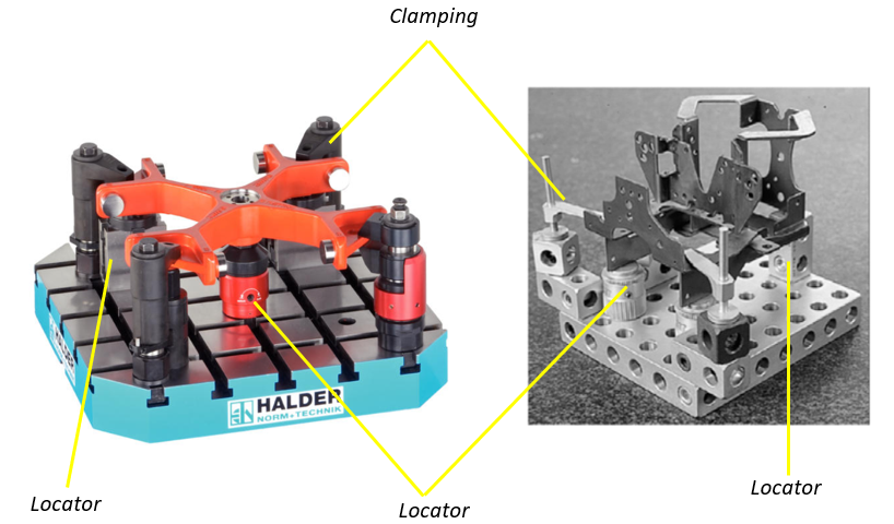
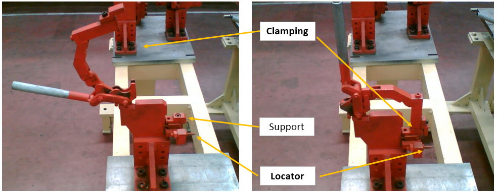
Examples of fixturing systems for rigid and non-rigid (sheet-metal) parts are shown in figure 2. From figure 2, we can see that real fixturing systems found in industry have complex shapes. These complex fixtures are to accommodate the complexity of various parts.
However, no matter how complex the shape fixtures are, they should have at least two elements: locator and clamping to be considered good fixtures. Some of them have additional elements: support and guide.
In figure 2 (left), a modular fixture is shown. This modular fixture can be re-configured to adapt and hold various types of the complex shapes of parts.
Some examples of jig (or fixture-jig) system are shown in figure 3. In figure 3, the jig system (since it is a fixture) also have the two fundamental elements that define a fixture, that are locator (in this case is also as support/base) and clamping. In addition, the jig system also has an additional element that can be used as a guide of a drilling tool to be able to achieve accurate drilling point/location (in this case, the jig example is shown in a machining process).
The additional guide element is the one that differ between an only fixture and a jig (fixture-jig). The fundamental characteristic of a jig system (to differentiate with an only fixture) is that a jig “interacts” with an actuator or end-effector of a robot in an assembly or measurement process or with a tool in a machining process.
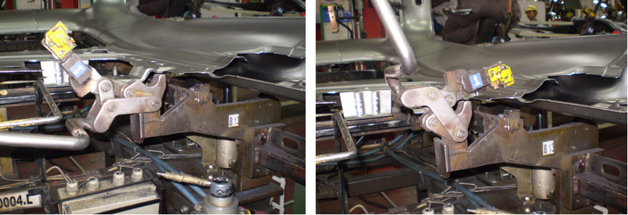
A common fixturing system for non-rigid (for example sheet-metal) parts is shown in figure 4. Fixturing systems for non-rigid parts are very common to be found in car body assembly. Because, a car body is constituted by many sheet-metal panels.
In figure 4, the fixturing system is shown when the fixture is in opened position (no parts) and in closed position (holding a sheet metal part). This type of fixture is usually combined together with other similar fixture to form a more complex fixturing system for complex non-rigid part, for example the big side panel and the roof panel of a car body (will be shown in later section).
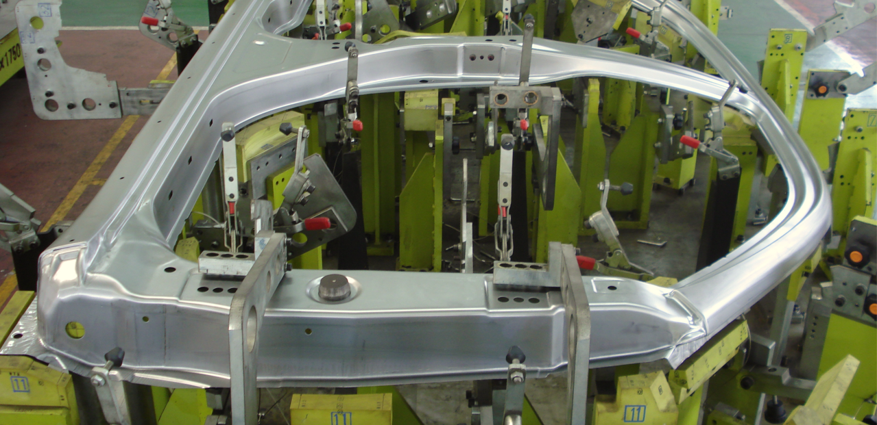
In figure 5, a real example of the assembly of a part of car body panel using a common type of fixturing systems used in automotive industries. In this figure, the fixtures are connected by a steel skeleton structure. This structure is very common for the fixturing system in automotive industry. The structure should be designed so that the structure is rigid enough (not bending) when providing forces to hold parts.
There are two types of locators:
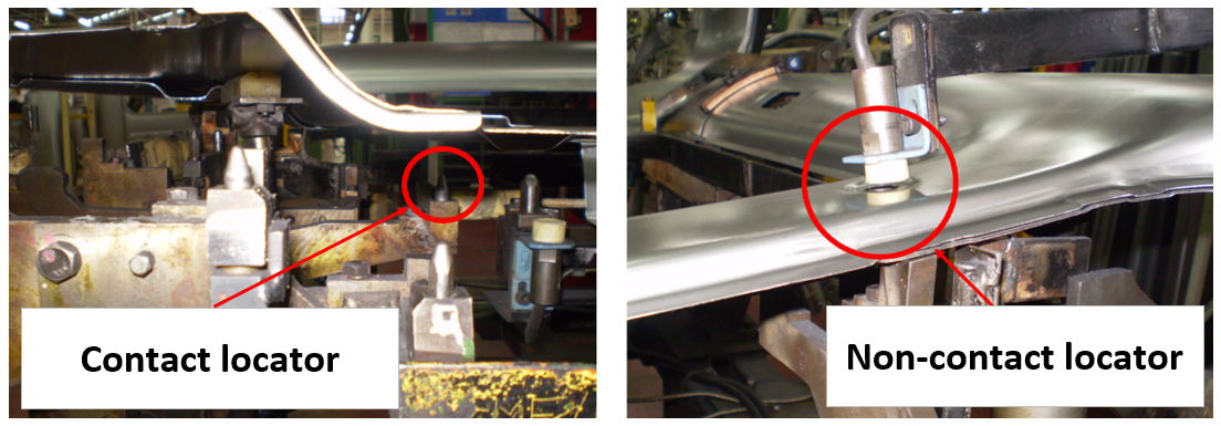
- Contact locator. This locator touches the surface of a part. Commonly, the contact locators are in the form of pins.
- Non-contact locator. This locator does not touch the surface of a part. Commonly, this type of locator uses proximity distance sensors to detect the feature (commonly holes) of a part.
In figure 6, the two types of contact and non-contact locators are shown. In figure 6, a contact locator is in the form of a pin (the most common form for locator) and a non-contact locator is in the form of a proximity sensor to detect a hole location of a part (to determine the part position).
Commonly, the proximity sensor is connected to the assembly system so that when there is no part or a wrong part detected, the assembly system is not active. By this system, an automatic assembly verification can be implemented to reduce assembly faults, such as joining incorrect parts.
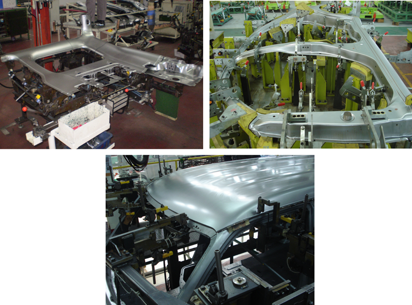
In figure 7, some real examples of fixturing system used in automotive industry are presented. No matter how complex the fixtures are, commonly, the fixtures are composed of a single common fixture joined with other fixtures. These many single fixtures are connected to steel skeleton structures designed based on specific shape of parts.
In figure 7, the assembly process is called a spot welding process. This process is a fundamental process in car body assembly. Sheet-metal panels of a car body is joined by melting a point area between two sheets pressed by a spot welding machine. The spot welding machine flows high current that generate heat. The heat melts the two panels so that the two panels joins together.
Conclusion
Fixturing systems are very important in assembly, manufacturing and measurement processes. A fixturing system should have at least two fundamental elements (to be defined as fixture):
- Locator
- Clamping
And may have other additional elements (depending on applications):
- Support
- Jig (guide)
One thing to remember is that no matter how complex the shape of a fixturing system is, we just need to consider and focus on the two fundamental elements of a fixture: locator and clamping. Very common, these two fundamental elements have basic prismatic shapes. In addition, we can consider the other elements: support and jig in special cases.
Finally, many complex fixturing systems are composed from many single simple fixtures joined together.
We sell tutorials (containing PDF files, MATLAB scripts and CAD files) about 3D tolerance stack-up analysis based on statistical method (Monte-Carlo/MC Simulation).