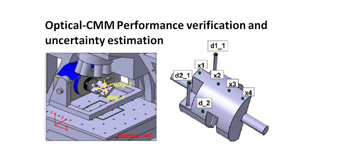
Optical coordinate measuring machine (Optical-CMM): Performance verification and measurement uncertainty estimation
Performance verification and measurement uncertainty estimation of an optical coordinate measuring machine (optical-CMM) are very important aspects assuring that the optical-CMM works within its specification and its measurement results are traceable to the definition of metre.
Performance verification and measurement uncertainty estimation of an optical coordinate measuring machine (optical-CMM) are very important aspects assuring that the optical-CMM works within its specification and its measurement results are traceable to the definition of metre.
In this post, we will discuss the performance verification and measurement uncertainty estimation for optical-CMMs and their measurements, respectively.
Fundamentally, the procedure of the performance verification follows ISO10360-3and the procedure for task-specific measurement uncertainty estimation follows ISO15530-4. However, there are some differences for optical-CMM implementations due to the nature of optical-CMM measurements and instrument configurations.
By the end of this post, we will understand the nature of optical-CMM measurement procedures and instrument configurations. In addition, we will have calibrated artefacts to performance verify optical CMMs and to estimate their “task-specific” uncertainty.
(Note: All 3D illustrations were created by using a CATIA 3D modelling software)
READ MORE: Optical coordinate measuring machine (Optical-CMM): Two fundamental limitations

Performance verification of optical-CMM
Performance verification of a CMM, including tactile (contact) and optical (non-contact), is a process to check or verify that the CMM operates within their manufacturer specification.
The parameter that represents a CMM accuracy specification is called maximum permissible error (MPE). MPE is the maximum value of error from a measurement result of a CMM. The international de facto standard for CMM performance verification is ISO10360 series.
According to ISO10360 guides, a performance verification process is performed by measuring distances (that can be a distance between two sphere centre points or distance between two planes of calibrated artefacts) for minimum in seven directions.
The seven directions are: three linear axes (X,Y,Z) and four volume diagonal of the measuring volume of a CMM. All the measurements should cover at least 67% of the total volume size of the CMM. For each length measurement direction, five minimum different distances should be measured that covers at least 67% of the maximum distance of the measuring directions (ISO10360).
To perform a performance verification, calibrated artefacts are required. A proposal for calibrated artefacts used for the performance verification of an optical-CMM has been proposed [1,2].
The proposed artefact is suitable for focus variation microscopy (FVM). Although, the artefact can be generalised to various type of optical-CMMs with minimal modifications and the same performance verification procedures.
For an FVM instrument, there are two modes of operation and configuration:
- Separated or independent 3-axis and 1-rotation axis measurements
- Simultaneous 4-axis (3-axis linear+1-axis rotational) measurements
The difference between these two measurements causes the need of two different calibrated artefacts and their performance verification procedure.
FVM with independent 3-axis and 1-rotation axis measurement
For the performance verification of FVM with separate 3-axis linear and 1-axis rotational measurements, a calibrated artefact for this type of performance verification is shown in figure 1 below.
In figure 1, the spheres are arranged in such a way that on each measurement direction: linear and volume diagonal directions, there are five different distance measurements. This artefact is designed to verify 2-axis linear (X and Y) and 4 volume diagonal directions (ISO10360-2).
Note that there is no Z-axis linear direction measurement due to the nature of the FVM optical-CMM configuration.
Distance or length measurements are measured between two centre points among the sphere location combinations.
From figure 1, the two spheres placed at the edge of the artefact are used to performance verify the rotational axis of the FVM instrument based on ISO-10360-3.
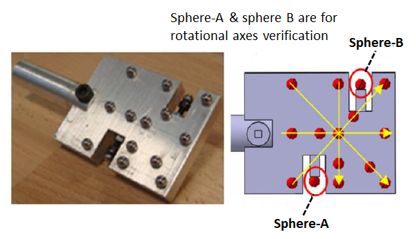
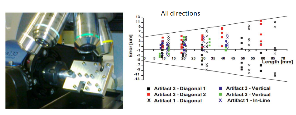
Figure 2 below shows the performance verification procedure by using the artefact shown in figure 1 above. From figure 2, the artefact is mounted on the instrument spindle chuck.
For 4-axis linear diagonal measurements, the artefact is rotated 45-degree both clockwise and anti-clockwise. From these 45-degree rotation, 4-diagonal length measurements can be performed.
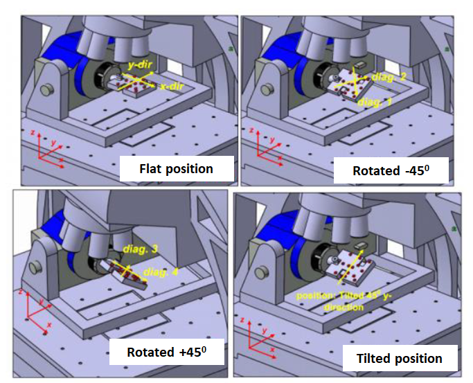
Figure 3 below shows the results of the performance verification of an FVM using the artefact and the procedure. From figure 3, the MPE of the FVM instrument is $(\pm 5+ \frac{L}{8}) \mu m$.
FVM with simultaneous 4-axis (3-axis linear+1-axis rotational) measurement
For the performance verification of FVM with simultaneous 4-axis (3-axis linear+1-axis rotational) measurement, the artefact and the performance verification procedure are shown in figure 4 and figure 5, respectively [2].
The main idea of this artefact is that the spheres are arranged in such a way that when the FVM performs a 4-axis measurement, the measurement trajectory will be in a form of linear diagonal measurements (due to the nature of FVM that the objective lens always from the top).
To achieve those linear diagonal measurements, the FVM need to use its 3-axis linear motion and 1-axis rotational motion simultaneously. The rotational movement is required to bring the sphere up so that it can be measured by the FVM objective lens.
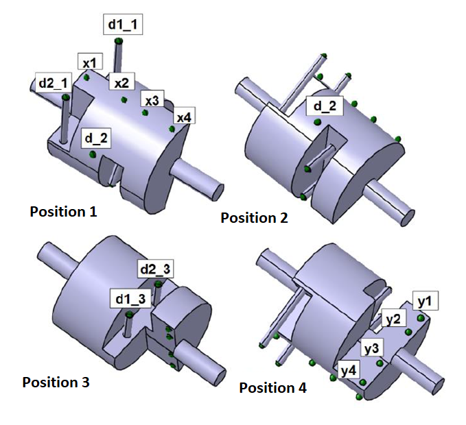
Figure 5 below shows the performance verification procedure with the 4-axis artefact. In figure 5, by using the artefact, the FVM should move simultaneously the 2-linear axis (X,Y) and its rotational axis to be able to measure four volume diagonal distance.
During the procedure, we need to interchange the chuck clamping between the two ends of the artefact. Due to this chuck interchange, the repeatability of the chuck when holding the end of the artefact will contribute to the rotational error of the FVM and hence will affect the MPE of the FVM.
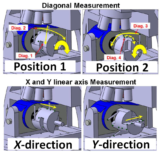
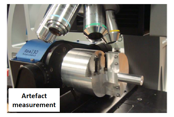
Figure 6 below shows the manufacture of the artefact and the real performance verification procedure. As we can see from figure 6, the weight of the artefact affects the MPE of the measurement due to the cantilever effect on the setup.
Note that the farther the sphere from the clamping point (the chuck), the larger the deflection error due to the cantilever effect (causing higher MPE).
Measurement uncertainty estimation of optical-CMM
Measurement uncertainty estimations for optical-CMM include uncertainty contributors that are not relevant for tactile-CMM but they are relevant for optical-CMM. Those factors are light and material (its surface topography and composition).
For “Task-specific” measurement uncertainty for optical-CMM based on microscopy, a proposal to estimate the measurement uncertainty by using Monte-Carlo method has been proposed [3].
The Monte-Carlo (MC) simulation is based on ISO15530-4, but the MC simulation considers the spatial correlation on the data points captured by an optical-CMM.
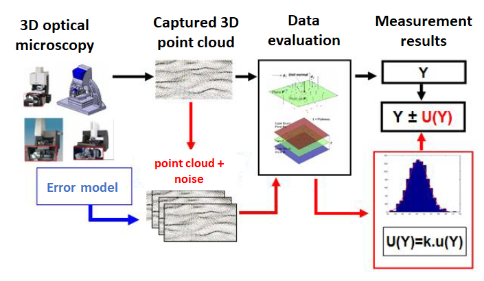
Figure 7 below shows the procedure of implementing MC simulation for “task-specific” measurement uncertainty by optical CMM. Briefly, the MC simulation in figure 7 is explained as follow:
- A real measurement of a part by using an optical-CMM is performed
- From the captured points obtained from the measurement, a dimensional or geometrical measurement $Y$ is calculated, for example a flatness measurement
- From the same point cloud, the points are perturbed by MC simulation. The MC simulation generate errors for each point cloud coordinate so that the spatial position of the points changes
- The MC simulation is repeated for a large number of repetitions
- From each MC simulation run, the same dimensional or geometrical measurement (in this example flatness) is performed, and the results are stored
- From the stored results from the MC simulations, a standard deviation is calculated
- Hence, the standard deviation is the estimate of the “Task specific” uncertainty of the measurement $Y$
READ MORE: CMM measurement uncertainty estimation: ISO 15530-4
Conclusion
In this post, two important aspects of optical-CMMs are presented, they are: performance verification and “Task-specific” measurement uncertainty.
In the case of FVM instrument there are two types of measurement: separate 3-axis linear and 1-axis rotational motion and simultaneous 4-axis motion. Each type of measurement has different calibrated artefact for their performance verification.
Finally, a method to “Task-specific” measurement uncertainty of optical CMM has been presented. Especially for contributors, the behaviour of the light and material (composition and surface topography) contributes for the optical-CMM measurement uncertainty.
References
[1] Moroni, G., Petrò, S. and Syam, W.P., 2014. Four-axis micro measuring systems performance verification. CIRP Annals, 63(1), pp.485-488.
[2] Moroni, G., Syam, W.P. and Petro, S., 2016. Performance verification of a 4-axis focus variation co-ordinate measuring system. IEEE Transactions on Instrumentation and Measurement, 66(1), pp.113-121.
[3] Moroni, G., Syam, W.P. and Petrò, S., 2018. A simulation method to estimate task-specific uncertainty in 3D microscopy. Measurement, 122, pp.402-416.
You may find some interesting items by shopping here.