Coordinate measuring machine (CMM): Calibration, performance verification and measurement uncertainty estimation
Calibration, performance verification and measurement uncertainty estimation are important activities for coordinate measuring machine (CMM) machine and measurement.
Calibration, performance verification and measurement uncertainty estimation are important activities for coordinate measuring machine (CMM) machine and measurement.
Based on these activities, we can get a reliable measurement result by using CMM machines. Note that we should not be confused between calibration and performance verification as these two activities are completely different.
Based on VIM: International Vocabulary of Metrology (the main reference for all term definitions in metrology), the definition of calibration, performance verification and measurement uncertainty are directly quoted from the VIM as follow:
- Calibration:
“Operation that, under specified conditions, in a first step, establishes a relation between the quantity values with measurement uncertainties provided by measurement standards and corresponding indications with associated measurement uncertainties and, in a second step, uses this information to establish a relation for obtaining a measurement result from an indication”
In simple words, calibration can be defined as an activity to compare a measurement result with another measurement result obtained from another instrument with higher accuracy than an instrument we use (in this case CMM). This calibration step produces the uncertainty of the measurement result.
- Performance verification:
“provision of objective evidence that a given item fulfils specified requirements”
In simple words, performance verification is an activity that a measuring instrument operate as the stated accuracy from its manufacturer.
- Measurement uncertainty:
“non-negative parameter characterizing the dispersion of the quantity values being attributed to a measurand, based on the information used”
In other words, uncertainty is the range of which the true value of a measurement result lies in between the range (uncertainty value). We will get this uncertainty estimation from a calibration process.
Note that measurement uncertainty is associated to a measurement result and not to an instrument.
The definitions above applied to all types of metrologies, such as dimensional, geometry, pressure, force, amount of substance, light intensity, electrical resistance and many other measurements.
(Note: All 3D illustrations in this post were created by using a CATIA 3D modelling software)
READ MORE: The fundamental concept of metrology.
CMM calibration
The calibration of CMM is commonly performed to quantify the volumetric error of a CMM as well as the uncertainty estimation of the volumetric error quantification [1].
The calibration process can be performed by using several methods, such as
- Using calibrated artefacts. The artefacts are calibrated with an instrument that is more accurate than a CMM under calibration
- Using laser tracker
- Using laser interferometer
Figure 1 below shows examples of the calibration of volumetric error of a CMM by using a laser tracker and using a calibrated artifact in a form of cylinder (hole) plate.
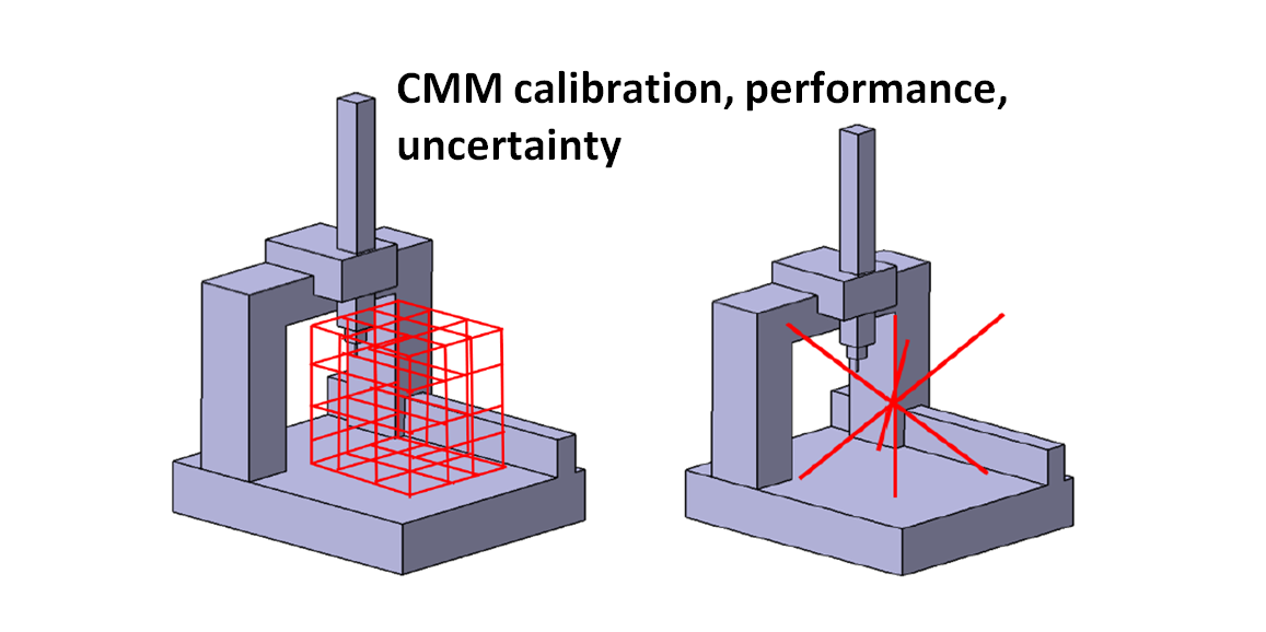
In principle, volumetric error is the location error (within the measuring volume) of the stylus tip of a CMM probing system.
This location error is defined as the difference between a detected location value read by the CMM controller and the actual stylus tip location inside the CMM measuring volume.
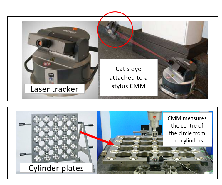
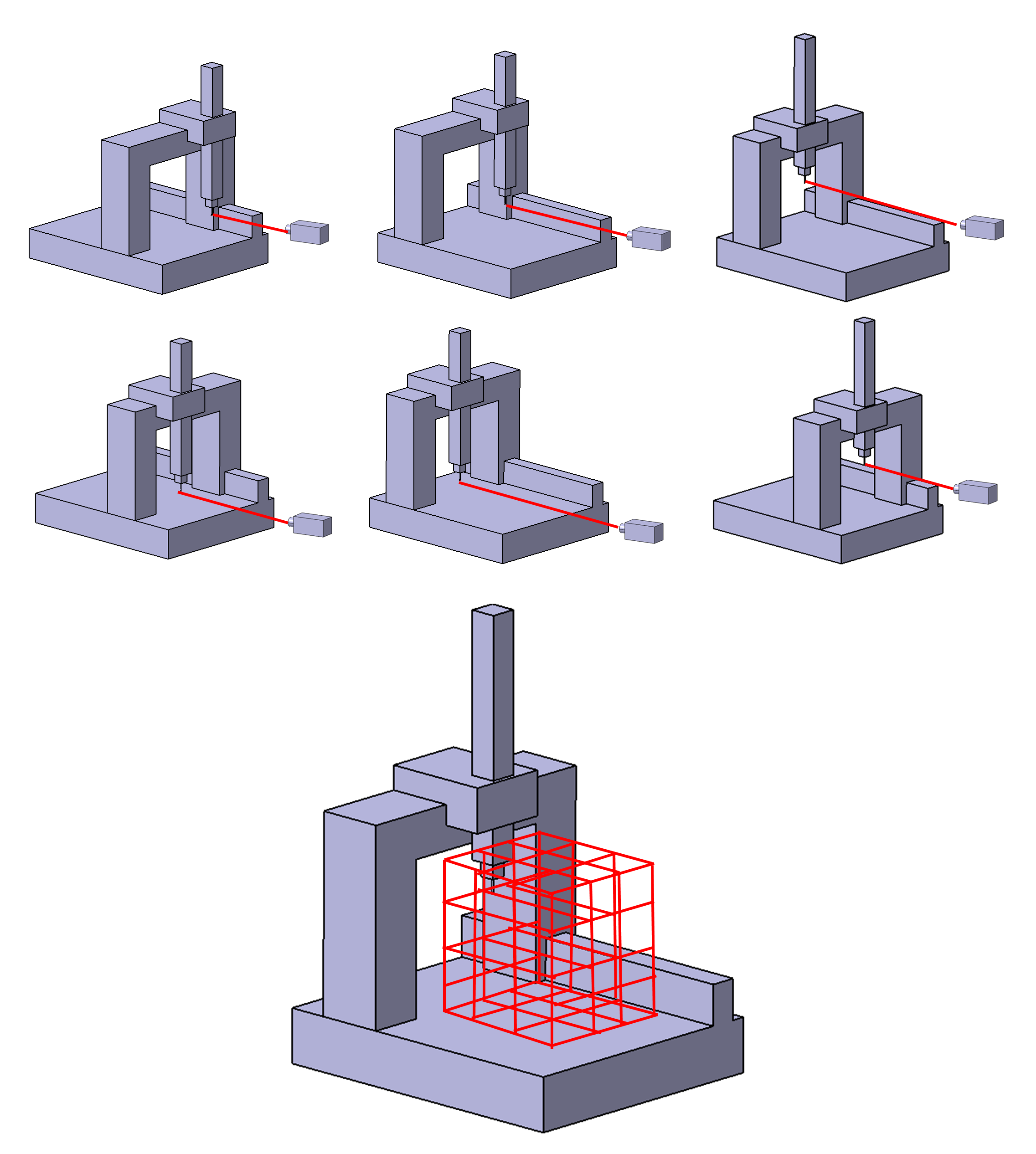
Figure 2 below presents an illustration of the volumetric error measurements of a CMM by using a laser interferometer. In figure 2, the volumetric error is measured one-axis by one-axis by using a laser interferometer. Constructing the main 3D volumetric error map (figure 2 bottom) is the final goal of the volumetric error calibration.
In figure 2, the location error of the stylus tip of the CMM is quantified for all possible tip locations within the CMM measuring volume.
The number of points or locations to quantify the errors are defined based on considering how high the resolution of the 3D volumetric error of the CMM that we want.
The higher the 3D volumetric error map resolution we want, the more accurate the volumetric calibration process, but the longer the calibration time required and higher the calibration cost will be [2].
To reduce the number of required locations to quantify the volumetric error of a CMM, a mathematical model representing the CMM can be developed and used.
With the use of the mathematical CMM model, only few location errors (representing the maximum volumes) of the stylus tip are required to quantify. The rest of the location errors within the measuring volume of the CMM can be interpolated by using the mathematical CMM model.
It is important to note that this calibration process is mainly performed by CMM manufacturers at their factory shop.
READ MORE: How to correctly present a measurement result.
CMM performance verification
Performance verification of a CMM is an important test procedure for a CMM including contact (tactile) and non-contact (optical) CMM.
Performance verification is a test to verify whether a CMM has a measurement accuracy according to the stated accuracy from the CMM’s manufacturer.
In other words, performance verification is a process to test the capability of a CMM to perform measurements and is not a process to test the positioning accuracy of the stylus tip of a CMM.
The international standard that commonly used for implementing a performance verification on a contact (tactile) CMM is ISO10360 part 1 to part 6.
The details of the ISO10360 part 1-6 are:
ISO 10360-1:
Contains terms used in the ISO 10360 standard series (especially ISO 10360 part 2-6). In addition, this standard also contains a standard sheet format to report the result of a CMM performance verification.
ISO 10360-2:
Contains a guide for performance verification of length measurement. This verification is related to evaluate the performance of a CMM structure.
To perform the performance verification for length measurement, five different types of length measurements with seven different measurement axis directions are required.
The seven measurement directions are three X,Y,Z axes and four volumetric diagonals within the CMM measuring volume.
For each measurement directions, the maximum measurement length is 67% of the maximum measurement length on that direction or axis.
These measurements usually used calibrated artefact in the form of a gauge bar or ball bar.
ISO 10360-3:
Contains a guide for performance verification of a CMM computer numerical controlled (CNC) rotary table.
The rotary table is usually called the fourth axis of a tactile CMM. In this performance verification, relative measurement is used.
Since we only need a relative measurement, a calibrated artefact is not needed as long as the artefact is rigid during the performance verification is performed.
ISO 10360-4:
Contains a guide for performance verification of a CMM probing system used for scanning-mode (continuous) measurement.
This verification process is performed by measuring a reference ball with scanning mode with a pre-determined scanning path.
ISO 10360-5:
Contains a guide for performance verification of a CMM probing system used for point-by-point (discrete) measurement.
This verification process is carried out by measuring a reference ball or sphere with point-by-point measurement and with the pre-determined number of points that have been pre-determined for their location.
ISO 10360-6:
Contains a guide to perform geometrical fitting used for performance verification based on ISO 10360-2, ISO 10360-3, ISO 10360-4 and ISO 10360-5.
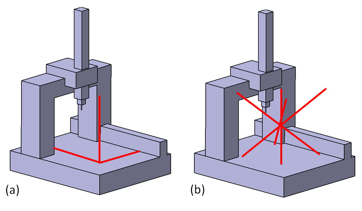
Figure 3 above shows the seven measurement directions for performance verification of a CMM length measurement based on ISO 10360-2 within the measuring volume of a CMM.
In figure 3, the seven directions are three directions along X,Y,Z axes and four volumetric diagonal within the CMM measuring volume.
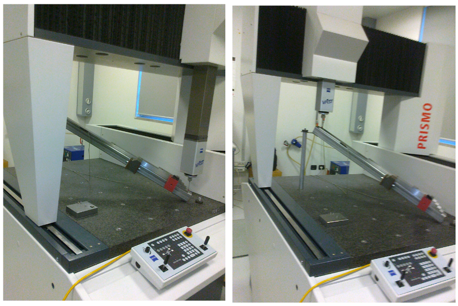
Figure 4 below shows an example of a real performance verification for length measurement of a CMM (based on ISO 10360-2) by using gauge bars as length reference.
The parameter to quantify for the performance verification of CMM length measurement (based on ISO 10360-2) is $MPE_{E,0}$. $MPE$ is “maximum permissible error” that states the maximum possible error that can be obtained for length measurement carried out by a CMM.
$MPE_{E,0}$ is a general parameter that describes the level of accuracy of a CMM that will be used for length measurement (dimensional measurement).
An example of the results of the performance verification of a tactile-CMM (based on ISO10360-2) is shown in figure 5 below.
In figure 5, from the performance verification process, the maximum error of the CMM, used for measuring a length up to 900 mm, is $\pm (2+L/300) \mu m$, where $L$ is in $mm$.
Hence, the $MPE$ of the CMM is stated as $MPE_{E,0}=\pm (2+L/300) \mu m $.
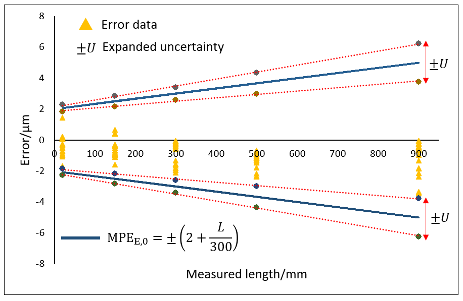
The uncertainty $U$ of the length error measurement (show in in figure 5 above) from the performance verification process is estimated by using ISO/TS 23165.
The uncertainty $U$ value is calculated as:
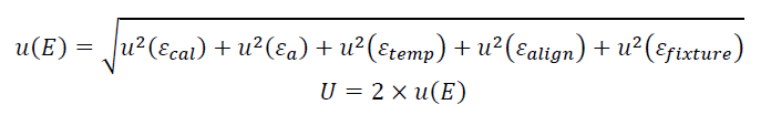
Where:
- $u(E)$ is the combined uncertainty
- $u(\epsilon _{cal})$ is the uncertainty of a calibrated artefact used in the performance verification
- $u(\epsilon _{a})$ is the uncertainty of coefficient thermal expansion (CTE) of the gauge bar used in the verification
- $u(\epsilon _{temp})$ is the uncertainty due to the temperature variation of the room where the verification process is performed
- $u(\epsilon _{align})$ is the uncertainty due to alignment error between a workpiece (the gage bar) and the machine coordinate system (MCS)
- $u(\epsilon _{fixture})$ is the uncertainty due to fixturing error, for example part deformation due to a large clamping force
READ MORE: The history and introduction of CMM: the inseparable relation between CMM and GD&T.
CMM measurement uncertainty
Uncertainty estimation for measurement results obtained from a CMM is governed in an international standard ISO 15530 series.
The methods for uncertainty estimation found in ISO 15530 are based on the Guide for Measurement Uncertainty (GUM) standard.
The GUM method is the main and fundamental source to estimate measurement uncertainty for any types of measurements, including non-dimensional and non-geometrical measurements, such as force, pressure, temperature and other measurements.
From the GUM standard, many specific measurement uncertainty estimation methods are derived, such as those found in ISO 15530 series, that are ISO/DTS 15530-2, ISO 15530-3 and ISO 15530-4.
Uncertainty estimation methods found in ISO/DTS 15530-2 and ISO 15530-3 estimates uncertainty by applying spread-sheet method that is tailored for CMM measurements with specific uncertainty contributors.
Meanwhile, the method found in ISO 15530-4 is based on Monte-Carlo simulation. The method based on ISO 15530-4 is the most used method for CMM measurement uncertainty estimation in industry. Because, in industry, tactile-CMMs are very common and main measuring instruments for dimensional and geometry measurements.
A brief summarised explanation about measurement uncertainty estimation methods based on ISO/DTS 15530-2, ISO 15530-3 and ISO 15530-4 are as follow.
ISO/DTS 15530-2
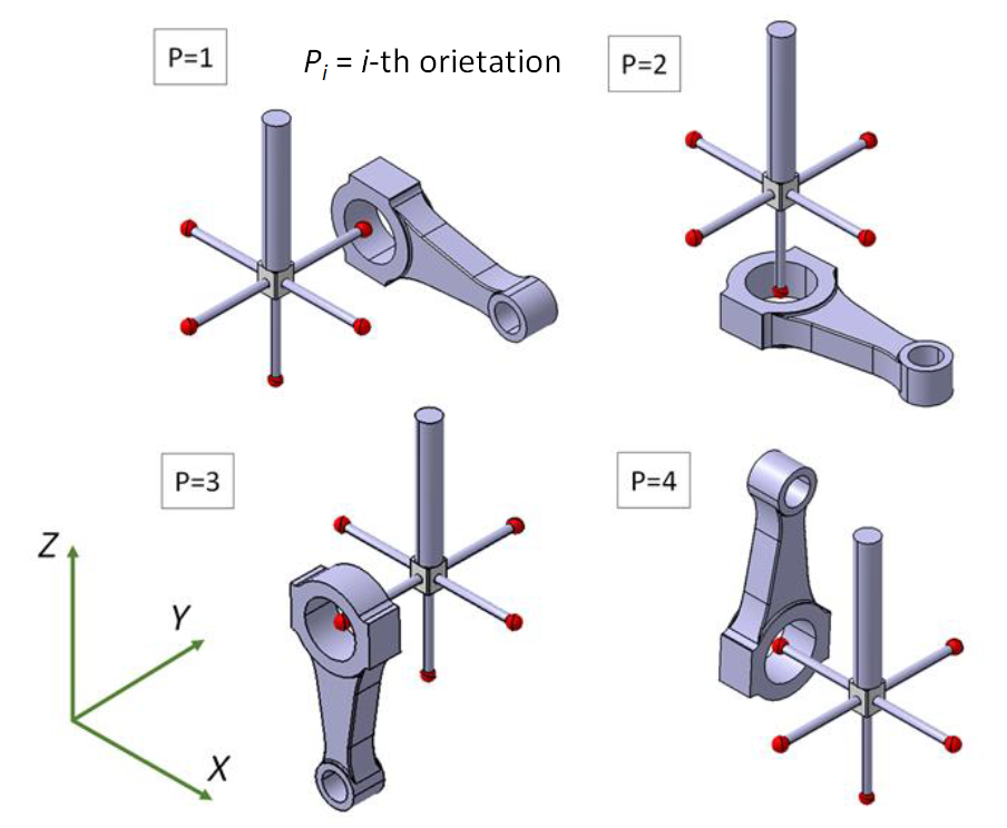
Uncertainty estimation method based on ISO/DTS 15530-2 is a method that uses the application of measurement by using multiple sampling and orientation strategies.
In the context of CMM, to estimate the uncertainty of a part measurement, we measure the part with different positions and orientations. The CMM that we use should be periodically performance verified so that the CMM is operating under its manufacture specification.
Figure 6 below show the example of ISO/DTS 15530-2 implementation to estimate a measurement uncertainty. In figure 6, a diameter measurement of a piston is presented.
To estimate diameter measurement uncertainty, we measure the piston at four different positions and orientations. There is no calibrated artefact used in this method (only a performance verified CMM). However, the uncertainty estimation is specific for this diameter piston measurement.
ISO 15530-3
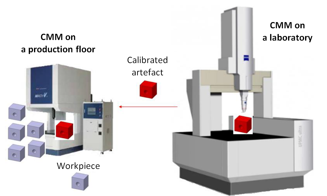
The method to estimate measurement uncertainty based on ISO 15530-3 uses a calibrated artefact with similar shape (and material) of a part that we want to measure. This method is common to be used in industry. Especially, to estimate the uncertainty of part measurement where the parts are mass-produced.
Figure 7 below shows the illustration of ISO 15530 implementation to estimate measurement uncertainty.
In figure 7, a calibrated artefact that has similar shape and material with the part that we want to measure. The total uncertainty will be the combination of the calibrated artefact uncertainty, measurement repeatability and reproducibility and uncertainty due to environment (temperature) variation.
ISO 15530-4
The uncertainty estimation method based on IS 15530-4 is motivated by the drawback of the methods presented in ISO/DTS 15530-2 and ISO 15530-3 mentioned above.
This method estimate is very suitable for “task-specific” measurement uncertainty. That is, a measurement uncertainty estimation is unique and representing a specific part, environment condition, measuring instrument used and measurement parameters set and other aspects, such as operator skill.
This method is based on computer simulation and can be applied to many different instruments, measurement types and environment conditions.
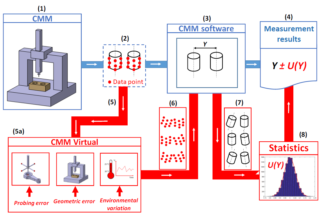
Figure 8 below shows the uncertainty estimation method based on ISO 15530-4. In figure 8, some points are samples by using a real CMM. The points are sampled from a real part that we want to measure.
Then, the sampled points are perturbed by adding noises by a computer simulation process. the noises are designed to represent a real measurement condition and relevant uncertainty contributors for the measurement.
This simulation step is repeated into many numbers of iterations. From the total simulation results, a standard deviation value is calculated and is used as the estimate of the uncertainty.
The advantages of this ISO 15530-4 uncertainty estimation method are:
- Flexible. Can be implemented into various types of measurements, parts and environment conditions.
- Cheap. Do not need a calibrated artefact and many real physical measurements.
- Easy to implement. The method can be used by many operators without the knowledge of the measurements.
- Minimal operator intervention. The simulation is performed by a computer.
- Fast. With the current computer power and affordability, the simulation to estimate a measurement uncertainty can be run rapidly.
READ MORE: Measurement uncertainty estimation: Spreadsheets method.
Conclusion
In this post, three important processes related to CMM and all other types of measurements are presented and discussed in details.
The important processes are calibration, performance verification and measurement uncertainty estimation.
All these processes are totally different and all together have an important role in measurements.
All reliable measurement results can only be achieved when the three processes have been performed correctly.
References
[1] Hocken, R.J. and Pereira, P.H. eds., 2012. Coordinate measuring machines and systems. Boca Raton: CRC press.
[2] Sładek, J.A., 2016. Coordinate metrology. Accuracy of Systems and Measurements.
You may find some interesting items by shopping here.