The probing system of tactile-CMM: Vector diagram and qualification process
In this post, the vector diagram and the mathematics behind the qualification process of a probing system are presented.
In this post, the vector diagram and the mathematics behind the qualification process of a probing system are presented.
Many coordinate measuring machines (CMMs) users may not know exactly how the qualification of the probing system (including its stylus system) of a CMM works. Many misunderstandings about this process have been going around. For example, the understanding of “the qualification system is the calibration process of a stylus system” is incorrect.
The qualification process is not a calibration process.
We will clearly present how qualification process and how it works to demystify the qualification process of probing system.
(Note: All 3D illustrations were created by using a CATIA 3D modelling software)
Let go into the details!
READ MORE: The probing system of tactile-CMM: Important aspects to consider for probing system.
The vector diagram of a probing system
To understand how a CMM machine works, it is fundamental to know the vector diagram of the probing system of a CMM.
To know as well as understand the vector diagram of a probing system, some mathematical foundations about the basic of homogeneous matrix and its operation as well as coordinate system transformation should be understood.
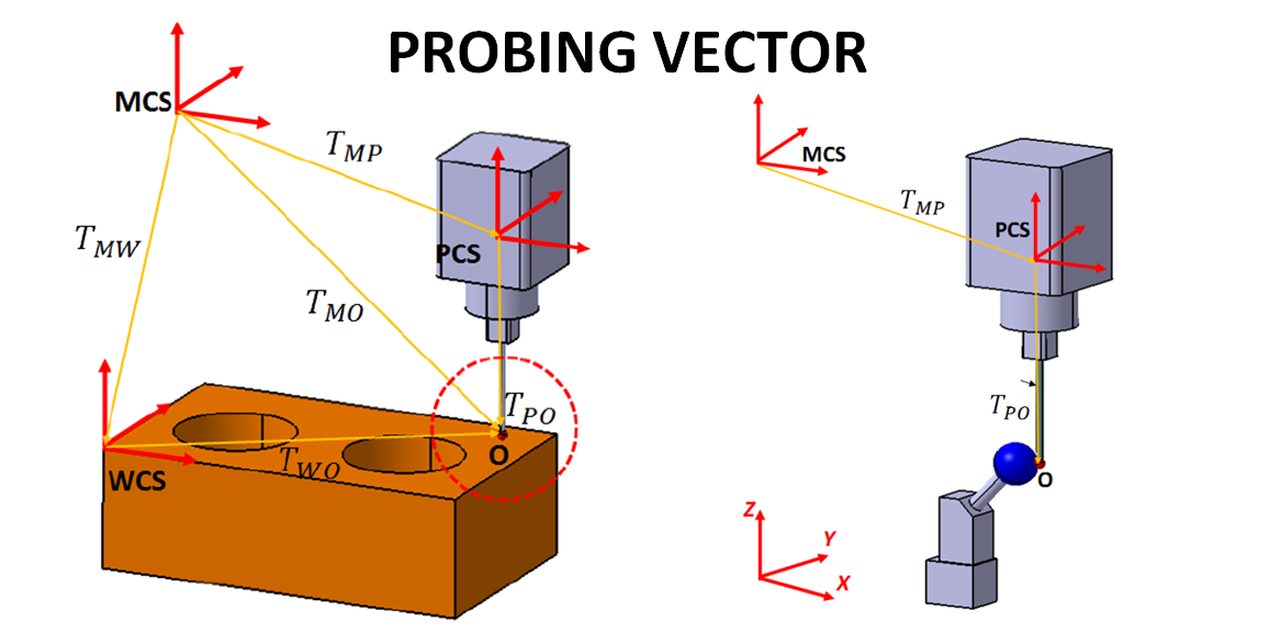
Figure 1 below shows the general vector diagram of a contact probing system on CMM.
From figure 1 above, there are three types of coordinates system for a tactile-CMM machine, that are:
- Machine coordinate system (MCS)
- Workpiece coordinate system (WCS)
- Probing coordinate system (PCS)
In principle, measurements with a CMM have a reference coordinate system based on WCS. However, the controller of the CMM reads all encoder positions in X-, Y- and Z-axis based on MCS.
Hence, a coordinate system transformation from the MCS to WCS (and otherwise) should be calculated. This coordinate system transformation should go through via the probing PCS.
Based on figure 1 above, the chain of coordinate transformations is explained as follow.
The main purpose of various coordinate transformation processes is to know the contact location of point O, that is the contact point between a measured surface and the stylus tip with respect to the MCS (see figure 1).
The location of point O with respect to the MCS is represented by $T_{MO}$. Meanwhile, all CMM measurements, after alignment process , point O has a reference with respect to the WCS that is represented by $T_{WO}$ (see figure 1).
Hence, the chain of coordinate transformation from the MCS to WCS should be reconstructed.
The process to reconstruct the chain of coordinate transformation from the MCS to WCS is explained as follow. A coordinate transformation from the MCS to O is firstly reconstructed as follow:
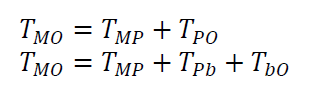
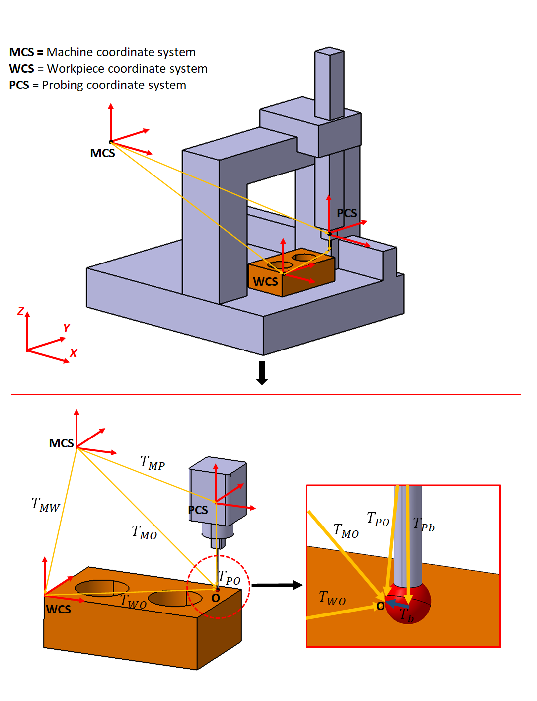
Where $T_{MP}$ is the coordinate transformation from the MCS to PCS on the probe head of a CMM, $T_{PO}$ is the coordinate transformation from the PCS to point O, $T_{Pb}$ is the coordinate transformation from the PCS to the centre of stylus tip and $T_{bO}$ is the coordinate transformation from the centre of the stylus tip to point O.
These chains of coordinate transformation will be established after the qualification process of the probing system (and stylus) of a CMM has been performed.
After the chain of coordinate transformation from the MCS to point O via the probing system is established (from a probing qualification process), the chain of coordinate system transformation from the MCS to WCS, represented as $T_{MW}$, can be established as well.
The chain of coordinate transformation from the MCS to WCS can be established via alignment process. the process can be formulated as follow:
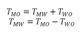
Where $T_{MW}$ is the coordinate system transformation from the MCS to WCS and $T_{WO}$ is the coordinate system transformation from the WCS to point O.
Hence, to construct a chain of coordinate transformation system that link or connect the MCS, PCS and WCS, a qualification process of a probing system and alignment process of a workpiece on a tactile CMM should be performed so that a measurement with the tactile-CMM can be performed.

The qualification process of a probing system
The process of the qualification of a probing system is a process to quantitatively know the characteristic and property of the probing head and stylus system of the probing system.
Similar to the vector diagram of probing system, to fully understand this qualification process, readers should have some basic understandings of homogenous matrices and coordinate transformation system.
The main purpose of a probing qualification system is to know the length and orientation of the stylus of a probing system and to know the diameter of the stylus tip of the probing system.
In other words, the probing system qualification is to determine the values of the element of transformation matrix $T_{Pb}$ and $T_{bO}$ (see the previous section above).
The matrix $T_{Pb}$ is the transformation matrix from the PCS to the centre of the stylus tip. That is when we know the values of the element of matrix $T_{Pb}$, it means that we know the length and orientation of the stylus system.
Meanwhile, the matrix $T_{bO}$ is the transformation matrix from the centre of the stylus tip to point O. That is, when we know this matrix $T_{bO}$, it means that we know the diameter of the stylus tip (see figure 1 above).
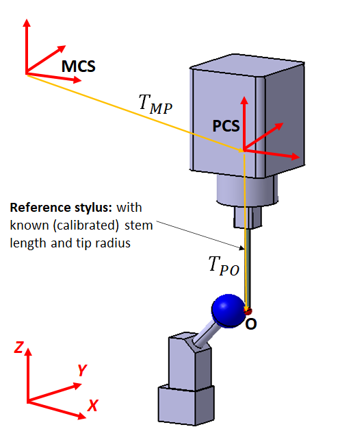
Figure 2 above shows the transformation chain of the probing system of a tactile-CMM that connects the MCS and point O.
Mathematically, the results of the probing qualification process are to determine the element values of $T_{PO}=T_{Pb}+T_{bO}$.
There are two main steps for probing system qualification, that are:
- STEP 1: to know the location of the centre point of a calibrated reference sphere with known diameter (as shown in figure 3 below)
- STEP 2: to know the length and orientation of a stylus stem and the diameter of a stylus tip (as show in figure 4 below)
STEP 1: Probing system qualification process
Step 1 of probing qualification is to calculate the location of the centre of a reference sphere used for the qualification process. In this step, a calibrated reference stylus is used (with known length and orientation as well as tip diameter). This reference stylus is always available for any tactile-CMM.
In this step, since we are using the calibrated or reference stylus, the stylus length and orientation ($T_{Pb}$) and its tip diameter ($T_{bO}$) as well as the diameter of the reference sphere are known. These known values are from a calibration process (usually performed by a CMM manufacturer) with very small measurement uncertainties.
In this process, the stylus used is a special stylus that is always available for any tactile-CMM. This special or reference stylus is made of special material (metal) that is stronger than the material used for other styluses to be qualified for performing measurements (we called “measuring stylus”).
Not only stronger, the material used for the special or reference stylus also has higher long-time stability with respect to measurement environment variations (temperature, pressure, humidity, etc) than other “measuring styluses”.
Since the length and orientation of the reference/special stylus stem/shaft are known, then the transformation matrix from the MCS to point O (in this case is the contact point between the stylus tip and the surface of the reference sphere) via PCS has been established.
This transformation is represented as $T_{PO}=T_{Pb}+T_{bO}$ as shown in figure 1 and figure 2 above.
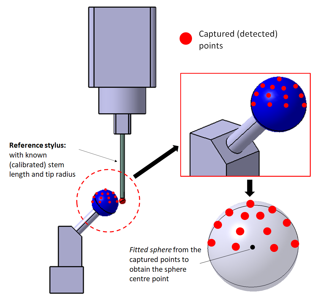
Figure 3 above shows the step 1 of probing qualification process. In figure 3 above, the qualification process is performed by capturing points on the surface of a reference sphere for as many as 32 points. These 32 points cover half of the entire sphere’s surface.
Because this process uses a reference or special stylus with known length, orientation and tip diameter, the location of the 32 points can be known with respect to MCS of the CMM. This known location with respect to MCS is due to the transformation matrices are known.
From those 32 points, to determine the centre location of the reference sphere, a least-square mathematical fitting process is applied to associate a sphere geometry to the obtained 32 points. After this sphere fitting process, the location of the sphere centre can be calculated.
The fitting process to associate a sphere geometry to the 32 points is an optimisation process defined as:
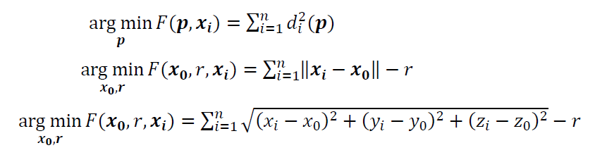
Where $ \textbf{x} _{0}=[x_{0},y_{0}, z_{0}] ^{T}$ is the centre of a fitted sphere, $r$ is the radius of the sphere and $ \textbf{x} _{i}=[ x_{i},y_{i}, z_{i}] ^{T}$ is the $i-th$ point.
STEP 2: Probing system qualification process
In this step 2 of probing qualification process, the main goal is to determine the length and orientation of a stylus (the configuration) to be qualified and used for measurement and the diameter of the stylus tip.
In other words, the transformation matrices $T_{Pb}$ and $T_{bO}$ (see figure 1 and figure 2 above) for the stylus to be qualified will be determined.
From the step 1 of qualification process above, the centre location of the reference sphere has been known. Then, the reference or special stylus used in step 1 is changed to a stylus that we want to qualify and will be used for measurements.
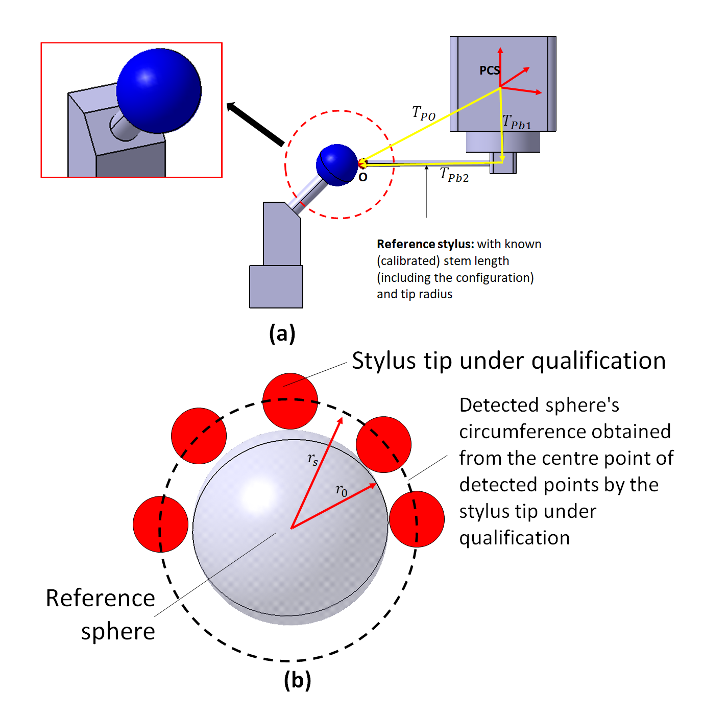
Figure 4 below shows the step 2 of probing qualification process. When the reference stylus has been changed with the stylus to be qualified, the transformation matrices $T_{Pb}$ and $T_{bO}$ are not known anymore.
Because, the length and orientation of the stylus stem as well as the stylus tip to be qualified and used for measurements are not yet known at the moment.
In figure 4 below, the matrices $T_{Pb}$ and $T_{bO}$ are represented as $T_{Pb1}$ and $T_{Pb2}$.
However, we already know the centre location of the reference sphere from the step 1. The next process is to remeasure the reference sphere, but with the stylus that we want to qualify and to use for measuring.
With the stylus to be qualified, we re-take 32 points on the reference sphere surface covering the half-of the whole sphere surface (see figure 4 below).
Hence, the sphere geometric fitting process is again applied to these obtained 32 points. The fitting process is the same optimisation process following the optimisation equation for circle fitting above above.
At the moment, those 32 points (collected with the stylus to be qualified) are the PCS positions that are recorded and stored in the controller memory of the CMM with the stylus to be qualified. These PCS positions are with respect to the MCS of the CMM.
The reason is that the length and orientation of the stylus stem and the diameter of the stylus tip to be qualified are not yet known so that the location of point O (see figure 1 and 2 above) with respect to the MCS of the CMM cannot be known at the moment.
After the sphere geometrical re-fitting process to those 32 points has been performed, then the centre location and the diameter of the reference sphere are now known. These centre location and diameter are different with those values obtained from step 1 (when using the reference stylus).
Because, the length and orientation as well as the stylus tip of the stylus to be qualified are different with the reference stylus. From these differences, the length and orientation of the stem/shaft and the diameter of the tip of the stylus to be qualified can be calculated.
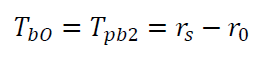
Firstly, the radius (and diameter) $T_{bO}$ of the tip of the stylus to be qualified is calculated as the difference between the radius of the reference sphere measured by the reference stylus $r_{o}$ and the radius of the reference sphere measured by the stylus to be qualified $r_{s}$, that is (see figure 4 above):
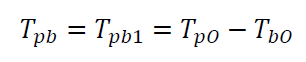
Secondly, the length and orientation of the stem of the stylus to be qualified $T_{Pb}$ can be calculated as the offset between the centre location of the reference sphere measured by the reference stylus and the centre location of the reference sphere measured by the stylus to be qualified, that is:
Finally, from the probing qualification process, we can obtain the length and orientation of the stem/shaft and the diameter of the tip of the stylus for measurement.
READ MORE: General procedures to operate a tactile coordinate measuring machine (tactile-CMM).
Conclusion
In this post, we have demystified the qualification process of the probing system of a tactile CMM.
It is important for tactile CMM users to understand the main purpose of probing qualification process. Because, this qualification process is compulsory to perform every time we want to use any tactile CMMs for measurement.
From this post, the qualification process is not a calibration process of the stylus of the probing system.
Instead, the main purpose of the qualification process is to quantify the length and orientation of the stem/shaft and the diameter of the tip of a stylus to be qualified and to be used for measurement.
You may find some interesting items by shopping here.