The probing system of tactile-CMM: Important aspects to consider for probing system
In this post, important aspects regarding the probing system of tactile-CMM is discussed. By knowing these aspects, we can improve the efficiency and efficacy of dimensional and geometrical measurements with tactile-CMM.
In this post, important aspects regarding the probing system of tactile-CMM is discussed. These important aspects include probing process steps, operational principles, operation modes, probing kinematic, probing force, stylus stem deflection, environmental effect, surface wear and plastic deformation, probing pre- and over-travel and probing error sources.
By knowing these aspects, we can improve the efficiency and efficacy of dimensional and geometrical measurements with tactile-CMM.
(Note: All 3D illustrations were created by using a CATIA 3D modelling software)
Let us deep dive into the important aspects for tactile probing system!
READ MORE: The probing system of tactile-CMM: The history, configuration and mechanism.
1. Tactile-probing process steps
In general, all tactile-probing processes have four common steps. These common processes or steps are applicable to all types of tactile coordinate measuring system (tactile-CMM) regardless the manufacturer of the CMM.
There are four main steps for probing process are:
- The motion of a stylus tip with a pre-determined speed toward the surface of a measured part
- The contact between the stylus tip with the measured surface
- The identification and recording of the spatial coordinate of the contact (by the probing head of the stylus) point between the stylus tip and the measured surface
- The retraction motion of the stylus from the measured surface to its reference position or to another point on the measured surface
2. Operational principles of tactile-probing system
For modern tactile-CMMs nowadays, the mechanism of tactile-probing is divided into two main types: touch-triggered probeand measuring probe.
Touch-triggered probe is the probe that initially invented by Sir David McMurtry. This touch-triggered probe can only have two types of response: contact or non-contact states.
Meanwhile, measuring probe of a tactile-CMM has an additional capability. This additional capability is to understand or detect the vector response of probing directions. That is, this probe can know approaching and retraction directions of a stylus tip. Measuring probe is divided into active and passive probe.
Touch-triggered probe is simpler than measuring probe. This simple construction causes the size and mass of touch-triggered probe become significantly smaller and lighter than measuring probe.
The production cost of touch-triggered probe is subsequently lower than measuring probe. Touch-triggered probe is very suitable for the measurement of simple dimension and geometry, such as length, diameter and flatness measurements.
Measuring probe has a more complex structure than touch-triggered probe due to its ability to sense the approaching and retraction directions of a stylus system. Measuring probe is very suitable to measure a free-form surface with complex curvature.
Measuring probe is comprised of a flexure system with attached strain gauges. From these flexure and strain gauges system, the probe can calculate the vector direction of a stylus tip when the tip touches the surface of a measured part.
3. Operation mode of tactile probing system
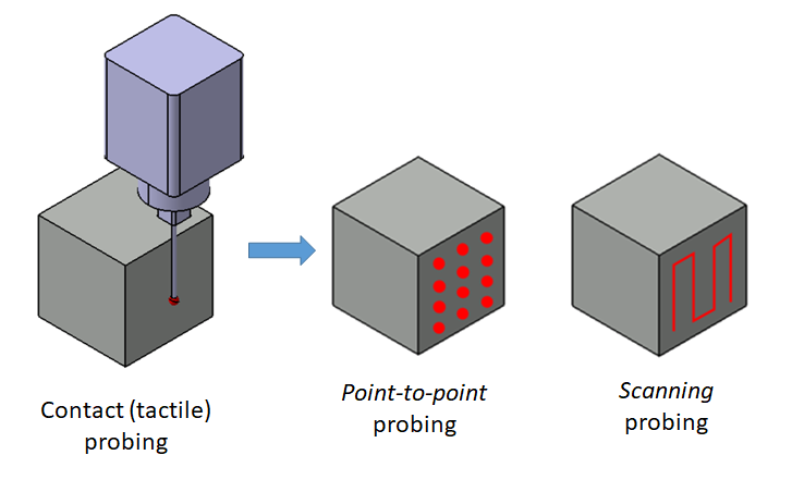
The operation mode of probing system is divided into two main steps: point-to-point probing and scanning probing.
Figure 1 below shows the illustration of point-to-point probing and scanning probing.
Point-to-point probing is the detection of points on the surface of a measured surface by one-by-one fashion. Meanwhile, scanning probing operates by following the contour of a measured surface (by constantly touching the surface during the following/scanning process) while at the same time collecting or recording the spatial coordinates of the touched points into the controller memory of a tactile-CMM.
Note that scanning probing can only be performed by measuring probing.
Point-to-point probing has a lower measurement uncertainty than scanning probing method. Because, in scanning probing mode, the dynamic of a CMM has a significant effect on measured points. However, the advantage of scanning probing is that this probing can collect significantly more points within a short period of time compared to point-to-point probing mode.
4. Probing system kinematic
The configuration of probing system is classified into two types: serial kinematic and parallel kinematic.
Serial kinematic has a stack configuration for the components that measure axes movements. Serial kinematic is usually used for a probing system with measuring probe.
Meanwhile, parallel kinematic configuration is usually used for touch-triggered probe. The reason is that, for touch-triggered probe, axis motion differentiations are not important because touch-triggered probe does not give information about probing vector, that is the approaching direction of a stylus tip to a measured surface.
READ MORE: General procedures to operate a tactile coordinate measuring machine (tactile-CMM).
5. Probing force and Hertzian contact pressure
Probing force, although very small, has a significant effect to the repeatability of the measured points on a surface.
Because, the probing force will affect the bending of a stylus stem or shaft, the deformation (both elastic and plastic) of a stylus tip and the linearity of the contact sensor inside a probing head.
Hence, active measuring probing is very useful to reduce the measurement uncertainty contributed from the probing system of a tactile-CMM. Because, the measuring probe can produce a constant probing force toward a measured surface.
In addition, the size of a stylus tip will directly affect the contact force between the stylus tip and a measured surface.
For common cases of conventional dimensional and geometrical measurements at macro-scale (mm-scale or more), such as gear measurements, engine components and other mechanical components, the size of stylus tip used for measurement is usually ranging from 1 mm to 8 mm with a static probing force ranging from $50 mN$ to $200 mN$. The repeatability of the spatial coordinate of measured points is usually in the range of $0.1 \mu m$ to $10 \mu m$.
A tactile-CMM can also measure parts or components at meso- to micro-, even nano- metre scale. For example, a tactile-CMM can be used to measure micro-lens, micro-gear and the nozzle of the fuel injector of an automotive engine.
The configurations of a tactile-CMM to measure those small or micro-scale parts are to use a very small stylus tip with diameter of $(0.1 -0.5) mm$ and very small probing force.
However, with a very small stylus tip, the pressure of the stylus tip to a measured surface will become large. This large contact pressure will affect the topography of the measured surface, for example, it can cause a plastic deformation following the shape of the stylus tip on the surface.
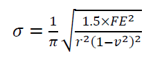
Stylus contact pressure to a measure surface is called Hertzian contact pressure. Although the contact force between a stylus tip to a surface is small, since the contact area of the stylus tip to the surface is very small, the Hertzian contact pressure will be large.
Hertzian contact pressure is formulated as:
And, $w_{0}$ is the elastic deformation of a stylus tip when contacting or touching a surface is formulated as:
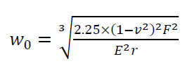
Where $F$ is the contact force of a stylus tip, $r$ is the radius of a stylus tip, $E$ is the effective Young modulus of a stylus tip material, $v$ is Poisson ratio.
$E$ is calculated as:
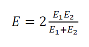
Where $E_{1}$ and $E_{2}$ are the Young modulus for a stylus tip and a measured part, respectively.
READ MORE: The history and introduction of CMM: the inseparable relation between CMM and GD&T.
6. Deflection of the stylus stem of tactile-probing system
Beside the effect of Hertzian pressure of a stylus tip on a measured surface, the deflection of a stylus stem or shaft can also reduce the accuracy of a probing system.
Because, when there is a deflection on the stylus tip, the recorded spatial coordinate of the contact point between a stylus tip and a surface will be different with the actual contact point coordinate. This difference is due to the coordinate transformation from the stylus tip to the machine coordinate system (MCS) of a tactile-CMM is different due to the deflection factor of the stylus step or shaft.
The deflection of a stylus stem is caused by the bending moment with value that is proportionally to the length of the stylus stem or shaft.
The stylus bending $w_{S}$ on normal probing direction (approaching or touching direction to a measured surface) is formulated as:
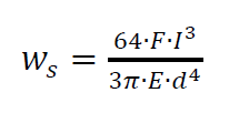
Where $F$ is probing force, $l$ is the length of stylus stem/shaft, $E$ is the Young modulus of a stylus stem material and $d$ is the diameter of a stylus stem/shaft (that is commonly in the form of cylinder).
The longer the stylus stem/shaft, the larger the bending will be on the stylus stem/shaft. The larger the stylus stem/shaft diameter, the smaller the bending will be on the stylus stem/shaft.
Hence, there will be a trade-off analysis to design a stylus stem to determine the length and the diameter size. Because, the length will affect the access capability of a stylus and the diameter size will affect the total weight of a stylus.
7. Environmental effects to probing system
The environment conditions (temperature, pressure, humidity and others) where measurements are performed will significantly affect the performance of a probing system.
Dust, that is on the atmosphere or ambient of the measuring environment and attached to the stylus tip of a probing system or a measured surface, can significantly reduce the accuracy of a measurement.
Vibration from ground or other sources can affect the displacement sensor of a tactile-CMM so that the scale reading can be noisy. Especially for non-contact (optical) probing system, vibration noise can propagate to a measured surface and cause blur effect on the image received at the sensor of the optical probing system.
This blurring can cause a false trigger, that is a situation where an optical probing system incorrectly detect a measured surface due to micro-scale displacement effects on the measured surface (due to vibration).
The increase of temperature during a measurement can cause thermal expansions on the components of a probing system, both the components that are in a probing head and on a stylus stem and tip.
8. Wear and plastic deformation on measured surfaces
The effect of wear and plastic deformation are dominant on tactile (contact) probing system. The stylus tip of a tactile-probing system will wear after some period due to repetitive frictions between the stylus tip and measured surfaces.
This tip wear will have a negative effect on a measures surface especially when the surface is measured by using scanning mode.
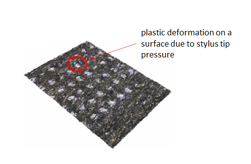
A small size stylus tip that is made of hard material (usually ceramic) tends to cause a micro-scale plastic deformation on a measured surface.
Figure 2 below shows an example of micro-scale plastic deformation on a measured surface due to Hertzian contact pressure between a stylus tip and the surface during a measurement. In figure2, semi-spherical patterns that follow the shape of the stylus tip are observed.
9. Pre-travel and over-travel motion of probing system
Pre-travel is the disposition (small movement) of a stylus when touching a measured surface before a contact detection is triggered. Meanwhile, over-travel is the disposition of a stylus when touching a surface after a contact detection is triggered.
Pre-travel has a variation that is affected by the asymmetric suspension system of a stylus, the moment of inertia of a stylus, sensor, the axis adjustment/setting of a CMM and probing force. The value of pre-travel disposition should be quantified and compensated to give a correct point coordinate or location. The quantification and compensation of the pre-travel of a stylus are performed during the qualification process of a stylus.
Over-travel is needed to give sometime for a stylus to decelerate when the stylus tip touches a surface. In principle, over-travel will be larger for a big surface compared to a small surface measurement. Usually, the amount of over-travel is in the scale of sub-mm or less.
10. Error sources of probing system
The main error source for probing system is divided into two classes: errors related to the feature of a measured part and errors related to the mechanical construction of probing system.
Errors related to the feature of a part include the condition of the surface topography of a part (such as the roughness and geometrical deviation), the deformation of a stylus tip when contacting with a surface, the deflection of a stylus stem/shaft due to contact with a surface and the effect of the geometrical deviation of a stylus tip.
Meanwhile, errors related to the mechanical construction of a probing system include the non-linear effect of the probing transducer to measure the stylus deflection, the effect of transducer sensitivity, the inhomogeneous reaction forces of the mass of a probing head and the accuracy of mechanical interface between a probing head and its stylus system (especially when changing the stylus types).
ISO 10360-4 provides guides to evaluate the probing error for scanning mode measurement. Meanwhile, ISO 10360-5 provides the guide to evaluate the probing error for point-to-point mode measurement.
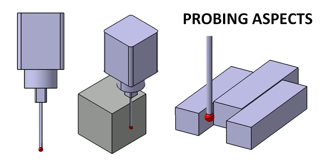
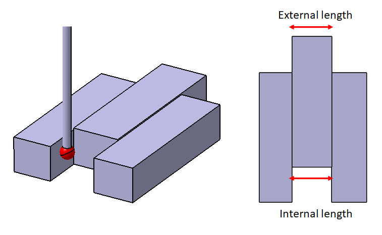
The hysteresis property of a probing system should also be quantified and evaluated. This hysteresis to understand the probing error when measuring the same length but with different approaching directions (inward or outward) as shown in figure 3 below.
The procedure to quantify the hysteresis of a probing system commonly uses three calibrated gauge block that is wringed (attached) together as shown in figure 3 below. These three gauge blocks are arranged such that the middle gauge block has both “internal and external length feature”.
The hysteresis is then quantified by measuring the internal and external length of the middle gauge block (figure 2). These types of measurement require two different probing or approaching directions to measure the same length with the same quantity.
Conclusion
Important aspects of probing system for tactile-CMM have been discussed in this post. At least, there are 10 important aspects to consider when we talk or evaluate a tactile probing system.
Probing system is one of the fundamental components of CMM. Because probing system is the sensor to detect whether a stylus has contacted a surface or not.
Among all 10 important aspects, there are few aspects that are quite not yet known by common CMM users, such as the effect of Hertzian contact pressure that can cause plastic deformation on the surface that we measure and the hysteresis property of a tactile probing system.
The property and characteristic between touch-triggered probe and measuring probe are also explained. Because, these types of probing system affect the decision to perform a scanning mode measurement and to measure complex free-form surfaces by using a tactile-CMM.
You may find some interesting items by shopping here.