The history and introduction of CMM: the inseparable relation between CMM and GD&T
The invention of coordinate measuring machine (CMM) is a direct consequence of the need to verify dimensional tolerances (GD&T). In this post, the history behind the invention of CMM as well as a brief introduction about CMM is presented.
The invention of coordinate measuring machine (CMM) is a direct consequence of the need to verify dimensional tolerances (GD&T).
In this post, the history behind the invention of CMM as well as a brief introduction about CMM is presented.
It was due to the creativity and curiosity of a FIAT engineer to solve problems of the need of many complex setups and manpower required to measure and verify GD&T tolerances and to automate these GD&T verification in factory-scale that propel the invention of CMM.
By understanding this history of the invention of CMM, we will understand that CMM and GD&T are inseparable.
Let us have a look at the history!
READ MORE: Coordinate measuring machine (CMM) - An introduction, types, considerations and applications
The history and motivation of the creation of CMM
CMM is a 3D measuring instrument that captures or senses spatial coordinate of the surface of a measured part. The spatial point capture method can be based on contact (tactile) or non-contact (optical).
The first CMM was made in between 1950-1960. The first made CMM was manufactured by a company in Scotland called Ferranti Ltd.
The initial motivation of the invention of CMM was to automate and speed up the measurement and verification of GD&T tolerances in an automated manufacturing system containing computer numerical controlled (CNC)-based production machines.
However, the first CMM made by Ferranti was not a truly CMM as per its definition. Because, this CMM was not yet integrated with a CNC system and it could not fully be used for 3D measurements (as per the definition).
In 1963, an Italian engineer, Franco Sartorio, who was a FIAT engineer at that time, has an idea to make CMM as a universal measuring instrument that can measure and verify various types of dimensional and geometrical (GD&T) tolerances.
Franco obtained his idea from observing the highly automated Ford factory when he visited Ford motor company in the USA. He was amazed with how the Ford automation system can significantly increase the productivity of the Ford automotive industry.
When he came back at Fiat in Italy, he found that with the current GD&T measurement and verification system for automotive parts at Fiat, the complete automation cannot be applied. Because, with conventional system, a high number of manpower and measurement setups are required to verify many parts with GD&T tolerances (see the next section).
Hence, Franco Sartorio formed a company called Digital Electronic Automation (DEA) in Torino (Italy) and produced the first fully functional CMM (as per the definition) with bridge construction. Nowadays, DEA is merged under Hexagon metrology as one of the main CMM producers in the world besides Zeiss and Mitutoyo.
There are two ways to measure and verify GD&T tolerances: measurement with dial-gauges (manual method) and with CMM (automated method).
READ MORE: Tactile CMM: The reference of dimensional and geometrical measuring machine in industry.

GD&T measurement and verification with conventional dial-gauge
Conventional GD&T measurements use a dial gauge or a combination of dial gauges and other supporting instruments. This method is used long time before CMM was invented.
The combination of dial gauges is even much more complex for GD&T measurement and verification with related features, such as perpendicularity, position and run out tolerances.
However, GD&T measurement using a dial gauge or a combination of dial gauges are still common at shop floors by technicians, especially for quick check of simple tolerances or for setting up equipment.
Commonly, only experiences and highly skilled technicians use this method to measure and verify GD&T tolerances, because with correct procedures, these measurements can give accurate and fast (for simple measurements) measurement results.
With dial gauges, measurements are performed by moving the dial gauges over a measured surface as much as possible to cover the part surface that is toleranced and to be verified. While moving the dial gauges, the motion range on the dial indicator is monitored to check whether the dial indicator point to a number that is lower or higher than a given tolerance value on the surface.
A feature is said to be within its tolerance if and only if during the movement of a dial gauge over a toleranced surface, the maximum indicated value on the dial indicator should be less or equal to the given toleranced value.
For example, when a part surface is given $flatness$ tolerance of $0.1 mm$, hence, to be said within tolerance, the maximum value pointed by the dial indicator of a dial gauge used to verify the tolerance should be less than or equal to $0.1 mm$.
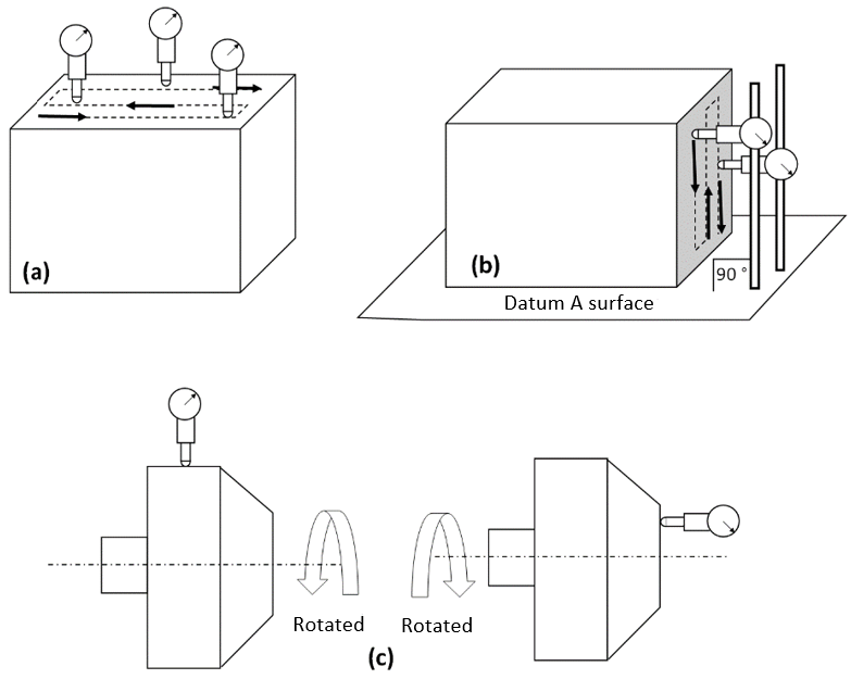
Figure 1 shows some example illustrations on various GD&T measurements and verifications using a dial gauge or a combination of dial gauges. These examples are still common to be found at shop floors and are performed by a highly skilled and experiences operators.
In figure 1, only shows few of many examples of the use of dial gauges to measure and verify GD&T tolerances. In practice, in industry, there are many methods and procedures to verify various types of GD&T tolerances with dial gauges.
The drawback of dial gauge method is that this method is manual and required high labor time and when the GD&T type is complex, the measurement procedure will require complex measurement setups and will take long time to produce measurement results.
GD&T measurement and verification with CMM
CMM is nowadays the most common method, or let us say modern method, to measure and verify GD&T tolerances. Although dial gauges method are still in use today in industry.
Not only to measure and verify GD&T tolerances, CMM can also be used to measure and verify conventional dimensional tolerances. Hence, CMM is a universal tool to measure various types of both dimensional and GD&T tolerances.
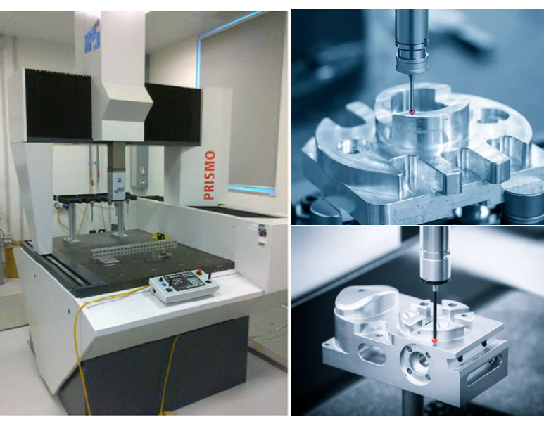
Figure 2 shows few examples for the use of CMM to measure and verify various GD&T tolerancing with one CMM machine.
With CMM, points on a measured surface that is tolerance are captured. Then, these points are mathematically process to associate nominal geometry and to derive the tolerance value calculated form the mathematical process. The algorithm to mathematically evaluate geometric tolerance from captured spatial points or coordinates is minimum-zone fitting.
In general, the standard CMM machine used in industry is contact CMM or tactile CMM. Contact/tactile CMM has various configurations, such as Cantilever, bridge and gantry. Bridge CMM is very common to be found at shop floors as this type of CMM can accommodate small to quite large parts. Gantry CMM is used for a very large parts.
Coordinate measuring machines (CMM): A brief introduction
CMM is considered as one of fundamental instruments to measure and verify dimensional and geometrical (GD&T) tolerances. In fact, the main reason CMM was made in the first place is to verify and automate various types of GD&T tolerances.
At the moment, CMM can be used to measure part at micro-scale to metre-scale. That is, the size of parts that can be measured with CMM (with different kind of CMMs) are from micro gears with diameter of 100 $\mu m$ to a bus-sized part.
Common applications for CMM are for example cylindrical part measurements, flatness measurements, roundness measurements of shafts or pins, perpendicularity measurements between two planar surfaces, run-out measurements, position measurements of hole centres, complex free-form surface measurements and other general dimensional length measurements.
The main ISO standards that govern CMM are ISO 10360 and ISO 15530.
- ISO 10360 is the ISO standard that governs about CMM performance verifications. This verification process is to check whether a CMM works according to its accuracy specifications.
- ISO 15530 is the ISO standard that governs how to estimate measurement uncertainties from CMM measurement results. This standard can also be applied or modified, and commonly it is, to estimate measurement uncertainties for other non-CMM measurements.
Besides ISO standard, German standards that are related to CMM and are common to use are VDI/VDE 2630 for CT-scan measurements and VDI/VDE 2634 for non-contact (optical) CMM.
In general, based on coordinate system, CMM is divided into two categories: Cartesian CMM and Non-Cartesian CMM.
1. Cartesian CMM
Cartesian CMM in general are constructed into 3-, 4- and 5-axes configurations in term of its axis movement. These motion systems are based on Cartesian coordinate where the axes motion has a common zero reference point.
Cartesian CMM can be divided into contact (tactile) and non-contact (optical) CMM. Types of Cartesian CMM (according to ISO 10360-1) are cantilever CMM, moving-bridge CMM, gantry CMM, fixed-bridge CMM and L-bridge CMM.
Figure 3 shows examples of various types of Cartesian CMM commonly found in industry. In figure 3, the examples show a moving-bridge CMM, cantilever CMM, gantry CMM and fixed-bridge CMM.
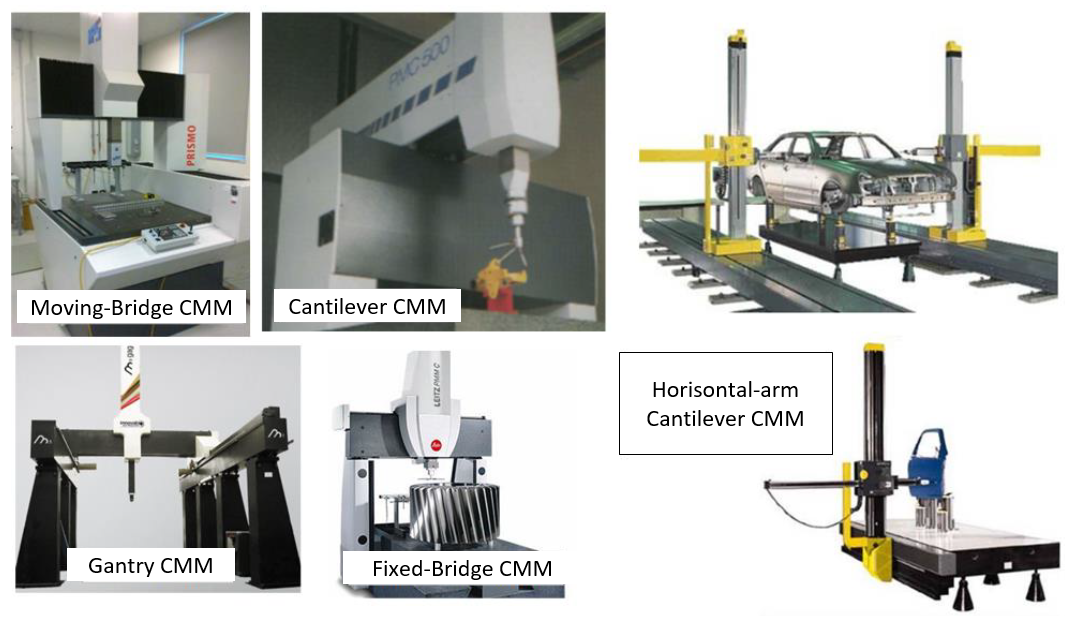
Each of these CMM configurations have their own advantages and disadvantages following their main use cases.
Moving-bridge CMM is suitable for the measurement of medium-to-big sized parts. This type of CMM is the most common used CMM in industry. The accuracy level of moving-bridge CMM is up to sub-micrometre and is the highest after fixed-bridge CMM.
Cantilever CMM is suitable for measurement situation where accessibility is the very important, for example the measurement of a car body. However, due to its cantilever construction, the measurement accuracy is lower compared to bridge CMM.
CMM gantry is suitable to measure a very big part. However, the accuracy of this CMM may be the lowest compared to other types of CMM. Also, due to its size, gantry CMM has the slowest measurement speed compared to other CMMs.
2. Non-Cartesian CMM
Non-Cartesian CMM is a CMM that is not based on Cartesian spatial X-Y-Z coordinate system. Very common, non-Cartesian CMM has cylindrical or spherical coordinate systems. Another characteristic of non-Cartesian CMM is that this CMM does not move when performing a measurement (for example a photogrammetry and CT-scan system).
Non-Cartesian CMM is also divided into contact (tactile) and non-contact (optical) systems. For examples, contact non-Cartesian CMM is articulated-arm CMM. Meanwhile, non-contact non-Cartesian CMM are Laser-tracker, photogrammetry and fringe projection.
Figure 4 shows various types of non-Cartesian CMM that are articulated-arm CMM, laser tracker, photogrammetry and fringe projection.
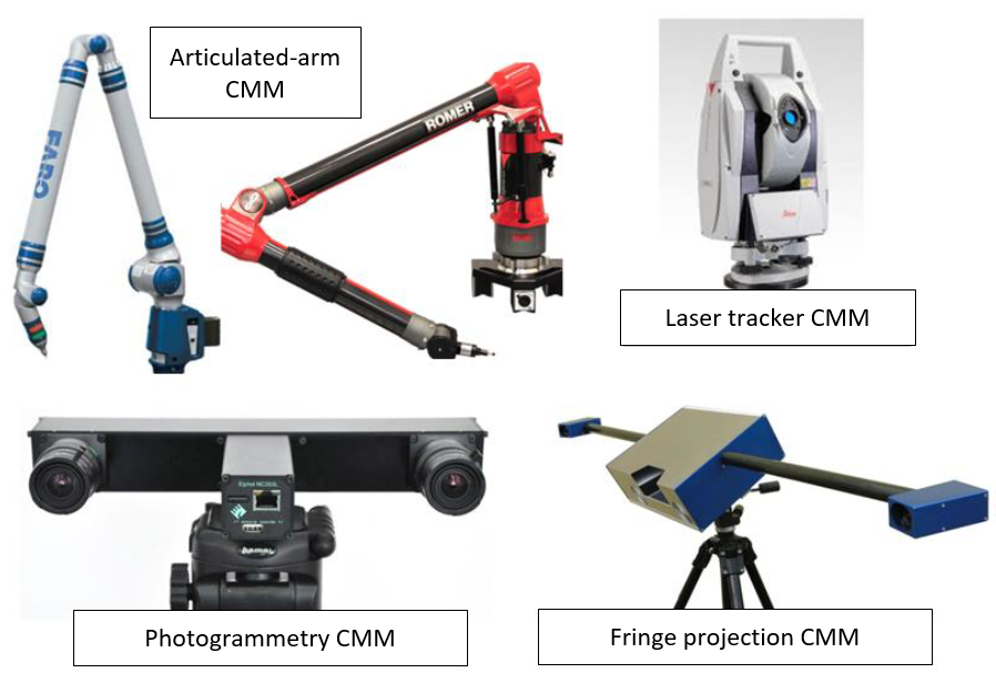
Articulated-arm CMM has a cylindrical coordinate system and laser tracker has a spherical coordinate system. Photogrammetry and fringe projection are commonly fixed on their location when performing measurements.
Very often, non-Cartesian CMMs are based on non-contact (optical) system, except for articulated-arm CMM that is a contact (tactile) system.
In general, non-Cartesian CMMs have lower accuracy compared to Cartesian CMMs. Except, laser tracker system that has a very high accuracy due to be based on laser measurement.
Conclusion
In this post, the history that explains the motivation of the invention of CMM is presented. By understanding the history behind CMM, we will know why GD&T and CMM are inseparable.
It was due to the effort to automate and speed up the measurement and verification of GD&T tolerances that propel the invention of CMM.
Nowadays, CMM is one of fundamental and common used measuring instruments at shop floors. CMM can be used as a general measuring instrument for both dimensional and geometrical tolerance verifications.
In addition, a brief introduction of CMM is also presented. Main types of CMM: Cartesian and non-Cartesian CMM are also explained with examples.
We sell all the source files, EXE file, include and LIB files as well as documentation of ellipse fitting by using C/C++, Qt framework, Eigen and OpenCV libraries in this link.
We sell tutorials (containing PDF files, MATLAB scripts and CAD files) about 3D tolerance stack-up analysis based on statistical method (Monte-Carlo/MC Simulation).