Coordinate measuring machine (CMM): An introduction, types, considerations and applications
Coordinate measuring machines (CMMs) have been well accepted as universal instruments to perform various types of dimensional and geometrical measurements. The measurements are performed by capturing or probing 3D spatial coordinate points (XYZ–coordinates) on the surface of a measured part.
Coordinate measuring machines (CMMs) have been well accepted as universal instruments to perform various types of dimensional and geometrical measurements. The measurements are performed by capturing or probing 3D spatial coordinate points (XYZ–coordinates) on the surface of a measured part.
CMMs are well used both in industry and laboratory environments. Not only 3D measurements, CMMS can also perform 2D dimensional measurements.
Due to the well-established traceability of tactile-CMMs (contact CMMs), they are often used as reference to verify or check the results of dimensional and geometrical measurements obtained from optical CMMs (non-contact-CMMs).
Currently, significant advancements in CMM’s technology have been achieves, for example, 5-axis probing system for tactile-CMM, high-speed tactile probing system and various king of optical CMM technologies, such as laser scanning and optical CMMs based on objective lenses (microscopy).
Nowadays, there are many specifically-designed CMMs to perform specific measurements, for example, the design is specifically to fit a specific production machine or to be able to follow a certain part shape.
The main ISO standards that govern CMM are ISO1060 and ISO15530. ISO10360 is for performance verification of CMM. Meanwhile, ISO15530 is for the determination of measurement uncertainty obtained from CMM measurements.
READ MORE: The history and introduction of CMM: the inseparable relation between CMM and GD&T
CMM as an established measuring instrument in industry: A historical introduction
Before CMM was invented, the measurements of part dimension and geometry in industry are considered as complex and repetitive tasks. These measurement tasks require many labours or man-hour.
Before CMM, mostly, dimensional and geometry measurements require many conventional instruments, such as dial gauge, gauge block, slip gauge, sine bar and other conventional instruments.
These conventional instruments are combined together to measure complex geometries. In addition, different combinations of these instruments are required for different dimension and geometrical measurements.
The requirement of difference combinations cause difficulties at shop floor, inability to automate production and finally cause bottle-neck in production flows (reducing production efficiency).
The creation of CMM was motivated by the need to automate the verification of geometrical and dimensional tolerancing (GD&T) on parts in an automotive industry (FIAT). They were used to support the automation of computer numerically-controlled (CNC) milling and turning machines.
Some examples of GD&T verifications are the measurement of location, cylindricity, flatness, roundness, perpendicularity, and run-out.
Nowadays, in manufacturing, CMMs, especially tactile-CMMs, have been a well-established dimensional and geometrical measuring instruments.
The behaviour and modelling of a tactile-CMM has reach a mature-level so that high-confidence measurement results can be obtained.
CMMs can be used to measure part from metre-scale (at mm-to-few micrometre uncertainty) to micrometre scale (at sub-micrometre or less uncertainty). Nowadays, some CMMs based on interferometry can even achieve nanometre-level uncertainty.
Types of CMM
There are many types of CMM. The types are based on characteristics used for classification.
In general, there are two types of CMM classification:
- Classification based on coordinate system used by a CMM
- Classification based on the interaction between a CMM and a part surface
Classification based on coordinate system used by a CMM
Types of CMM based on coordinate system are:
- Cartesian CMM
The classification based on this system is for CMMs that use Cartesian coordinate system (either 2-axes, 3-axes, 4-axes, 5-axes or up to 6-axes system).
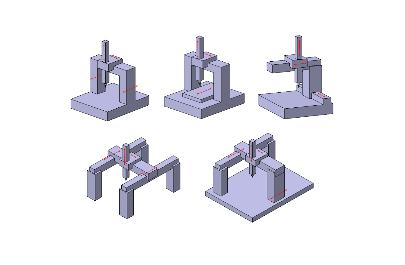
These types of CMM have an absolute zero reference. Figure 1 below shows various types of Cartesian CMM configurations.
From figure 1, Cartesian CMM is divided into five sub-categories: moving-bridge, fixed-bridge, cantilever, gantry and L-shapes CMMs
- Non-Cartesian CMM
The classification based on this system is for CMMs that use coordinate system other than Cartesian system, for example cylindrical or spherical coordinate systems.
Very often, these types of CMM are optical (non-contact) CMMs, for example, photogrammetry system, fringe projection and laser tracker.
However, there is also a tactile-CMM based on non-Cartesian system, for example, articulated-arm CMM.
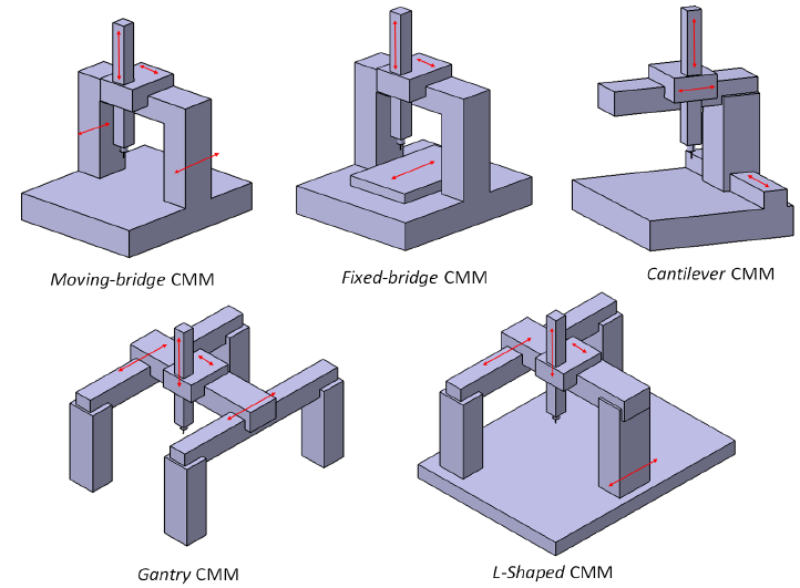
The various types of Cartesian CMM as shown in figure 1 are explained as follows:
- Moving-bridge CMM
This type of CMM is the most common type found in industries and laboratories. The popularity of this type of CMM is because this type of CMM has the balance among several aspects that are, to mention few, high measurement accuracy, relatively high measurement speed (compared to other types of Cartesian CMM) and the ability to measure parts with various shape and size.
This type of CMM has two-legs that move together in one-direction or one-axis. The other two-axes are from the motion of the bridge and its vertical axis (z-direction movement).
The moving-bridge have a “walking” phenomena (in micrometre or less scale) where the two legs are not exactly move at the same time. This “walking” phenomena introduce errors specifically for this type of CMM.
For five-axes moving-bridge CMM, the other two rotational-axes are mostly from the stylus system, that can rotate in along two different axes.
- Fixed-bridge CMM
This type of Cartesian CMM is the one that has the highest accuracy among all other Cartesian CMMs.
As per 2017, the accuracy level of this type of CMM can achieve $\pm (0.3+\frac{L}{1000}) \mu m$ where $L$ is in millimetre.
However, this CMM has the lowest measuring speed compared to any other Cartesian CMMs.
This type of CMM has two fixed-legs (fixed-bridge), hence the CMM table that move to give a one-directional axis that is provided by moving legs as in the case of moving-bridge CMM.
Hence, fixed-bridge CMM does not have a “walking” phenomena as found in moving-bridge CMM. This aspect is one of the cause fixed-bridge CMM has a higher accuracy than moving-bridge CMM.
Similar to the moving-bridge CMM, the other two-axes are from the motion of the bridge and its vertical axis.
- Cantilever CMM
Cantilever CMM is very often to be found in automotive industries. This type of CMM is mostly used to measure the body of assembled cars.
Cantilever CMM with horizontal arm has a long measuring arm that can access the surface of large component with cavities, like the body of cars.
However, cantilever CMM has a low accuracy compared to moving-bridge and fixed-bridge CMMs. Because, the cantilever arm induces a bending effect when the arm is at its farthest position. This bending effect contribute to measurement errors and reduce the CMM’s accuracy.
- Gantry CMM
This type of CMM has the largest measuring volume. Mostly, this type of CMM is used to measure parts with size of > 10 m.
However, this type of CMM has the lowest measurement accuracy compared to other Cartesian CMMs. Because, since it has a very large measuring volume, the geometric error (volumetric error) of the gantry CMM contribute to low measurement accuracy.
- L-shaped CMM
This L-shaped CMM is the most uncommon CMM compared to other Cartesian CMMs. Because, this L-shaped CMM is designed to measure parts with very specific shape.
The leg with L-shaped is to reduce the bending effect of the cantilever arm.
Classification based on the interaction between a CMM and a part surface
Types of CMM based on how the CMM interact with the part surface are:
- Tactile (contact) CMM
Tactile CMM is a CMM that mechanically touches the surface of a measured part. For example, tactile Cartesian CMMs (for example moving-bridge, gantry and fixed-bridge CMMs) and tactile non-Cartesian CMM such as articulated-arm CMM.
The fundamental advantage of tactile (contact) CMM is that this type of CMM physically touch the surface of a part by using a physical probe, such as a stylus tip from ruby sphere.
This process of physically touching a surface with a physical probe can be analytically modelled. That is, modelling a sphere rolling on a surface can be established.
Hence, the measurement results from a tactile CMM can be predicted with the analytical model and the error can be confidently evaluated and verified.
That is why tactile CMMs are always used to verify the measurement results of optical (non-contact) CMM.
Some drawbacks of tactile CMM are there will be a risk to damage the surface of a measured part due to the pressure from a small stylus tip. The smaller the stylus tip diameter, the larger the given pressure to a measured surface (Hertzian force).
The next drawback is that tactile CMMs relatively have slower measurement speed compared to optical CMMs. Also, the throughput of data points of measured from a surface of tactile CMMs is small compared to optical CMMs.
For example, by using a tactile CMMs, it may require hours of measurement time to produce thousands of data points from a measured surface. Meanwhile, for the same amount of data points, optical CMMs may require only few minutes of measuring time.
Another obvious drawback of tactile CMMs is that due to finite size of a tip, a tactile CMM has a limited access to features of a measured part. For example, a CMM with 1 mm stylus tip diameter, the CMM cannot measure a hole with diameter < 1 mm.
- Optical (non-contact) CMM
Optical CMM is a CMM that does not physically touch the surface of a measured part. This type of CMM uses optical method to probe a surface. Some common examples of optical CMMs are photogrammetry and fringe-projection systems.
Advantages of optical CMM are it can produce a large number of data points in relatively short measurement time, for example within less than one minute or few minutes, it can access small features on a part and it will not damage the surface of a measured part.
Meanwhile, drawbacks of optical CMM are as follows. The fundamental drawbacks is that optical CMM shine light to a surface and capture the reflected light to a sensor or photo-detector and then, with a certain algorithm and analysis, the surface is reconstructed from the detected reflected light on the sensor.
The problem is that, the interaction between light and surface is very complex and difficult to model. This difficulty causes the measured surface with an optical CMM cannot be analytically verified and leave some degree of doubt of the trueness of the reconstructed surface from an optical CMM and difficult to evaluate the uncertainty of the measurement.
The next drawback is that optical CMMs are significantly affected by the type of material of measured part. Very often, transparent or shiny polished surfaces are difficult to measure with optical CMM. Because, reflected lights from these surfaces are difficult to detect (due to saturation) by the sensor of optical CMMs.
Another drawback is that, due to numerical aperture (NA) of optical CMM, it is often very difficult to measure surfaces with around 90 degree surface slope.
Aspects that need to consider to select CMMs and their applications
There are various types of CMMs in the market including both tactile and optical CMMs. Considering the high cost of CMM, these many options cause difficulties to select a suitable CMMs for a certain type of measurements.
At least, there are five aspects that need to be considered to select the most suitable CMM for specific applications.
The considerations are:
- The accuracy of CMMs
- The instrument characteristic of CMMs
- The software ability of CMMs
- The sampling strategy capability of CMMs
- Other aspects to consider
The accuracy of CMMs
The main aspect to be considered in selecting a CMM is the accuracy level of the CMM. The required accuracy of a CMM is to be determined from how large the tolerance of parts that need to be measure.
For CMMs, according to ISO10360, the accuracy of CMMs is represented by maximum permissible error (MPE) specification.
Based on ISO10360, MPE is defined as $\pm (X+L/K)$, where $X$ is the accuracy level (for length measurement) of a CMM in $\mu m$, $K$ is a constant and $L$ is a measured length in $mm$.
An important thing to be remembered is that the variable $L$ in the MPE represents the effect of thermal expansion of a material and will affect the measurement accuracy of the CMM.
To determine the MPE of a CMM, a performance verification procedures, defined in ISO10360, has to be performed.
Beside accuracy, the uncertainty of measurement results perform by a CMM has to be also considered. This uncertainty value represents how much lack of knowledge about the measurement that we have.
Hence, the important things to be considered is what factors related to a CMM that contribute to the CMM measurement uncertainty.
Some common uncertainty contributors for CMM measurement uncertainty are, for example, temperature variation when a measurement is performed, the variation from sampling strategy used for a measurement, the geometric errors of a CMM and the dimensional variation of a part due to variation from a production process that makes the part.
Hence, both accuracy and expected measurement uncertainty of a CMM need to be considered hand-in-hand. Because, the accuracy of a CMM should be higher (smaller value) with respect to the expected measurement uncertainty to give space for other uncertainty contributors of the CMM.
A real example to consider accuracy and measurement uncertainty in selecting a CMM is as follow. If we want to measure the diameter of a cylinder with a specification of $(500 \pm 0.01)mm$, then we need to focus on the tolerance.
In this case, the tolerance range is $0.01 \times 2=0.02 mm$. Hence, a suitable CMM to perform this type of measurement task is a CMM that has an accuracy level of 10% of 0.02 mm. hence, the required accuracy level of the CMM is 0.002 mm = 2 $\mu m$ for length $L=500 mm$ to give “room” for other uncertainty contributors, such as from temperature variation and other environmental factors.
The next step is to select a CMM that has an accuracy level of < 2 $\mu m$ for $L=500mm$. For example, CMM A has an accuracy specification (MPE) of $\pm (1.2+L/500) \mu m$. This accuracy level of CMM A is not enough to measure the cylinder, because the total effective accuracy for the CMM to measure the cylinder is $1.2+500/500=2.2 \mu m$.
Another CMM B with an accuracy specification (MPE) of $\pm (1.3+L/1000) \mu m$. The effective accuracy of CMM B to perform the measurement is $1.3+500/1000=1.8 \mu m$. Hence, we can conclude that CMM B is the suitable CMM for the measurement task.
From the explanations above, the tolerance of a dimension we want to measure has an important role in selecting a suitable CMM to use. In addition, the expected uncertainty of measurement results of CMMs also need to be considered to define the required accuracy of a CMM to use.
Related to measurement uncertainty, an uncertainty budget of a measurement task with a CMM should be established. With this uncertainty budget, we can use to evaluate and understand which parts of the measurement processes give high uncertainty contributions so that we can improve that specific process.
For example, if from the uncertainty budget we observe that the most uncertainty contribution is from temperature variation during measurements, hence the most efficient way to solve it is to control the room temperature where the measurement takes place or compensate the temperature, instead of buying a more expensive CMM with higher accuracy!
The instrument characteristic of CMMs
The main characteristics of CMMs that need to be considered for selecting a suitable CMM are measuring volume, configuration, measured part’s weight, measuring speed and probing (sensor) type.
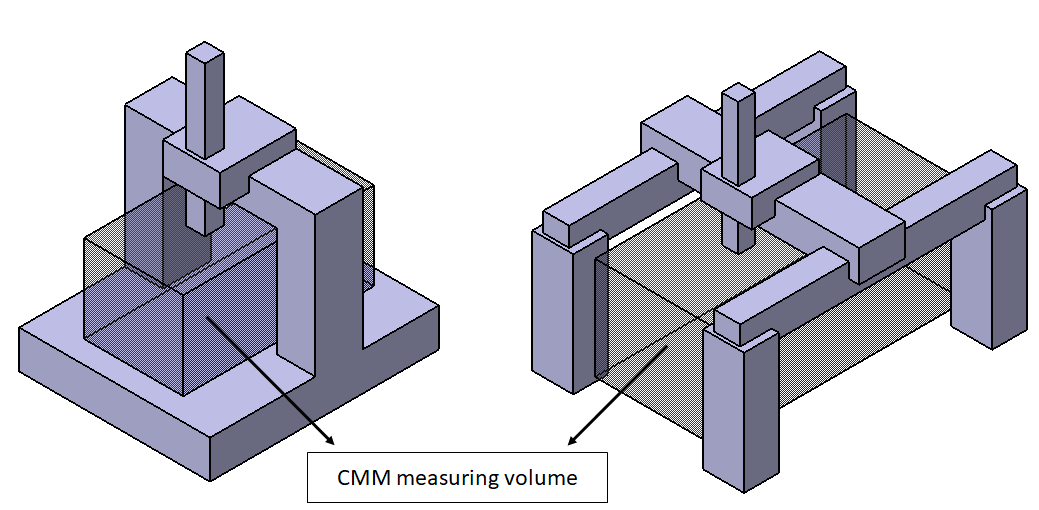
- Measuring volume
The measuring volume of a CMM is an area where the probe (sensor) of the CMM can access the area. In general, the measuring volume is in a cube or rectangular shapes that describe the maximum length, width and height of a measured part.
Figure 2 shows an illustration of CMM measuring volume for moving-bridge and gantry CMMs. A gantry CMM can have a very large measuring volume in metre x metre x metre scale. Meanwhile, a moving-bridge CMM usually has few hundreds mm x few hundreds mm x few hundreds mm up to the smallest volume of (10x10x10) mm.
- Configuration
The most common CMM configuration is the one with vertical measuring arm, because on that axis configuration, the effect of gravity is along the measurement direction so that there is no bending effect on this measuring arm.
Meanwhile, non-vertical arm of a CMM will be affected by gravitational force at different arm position or length.
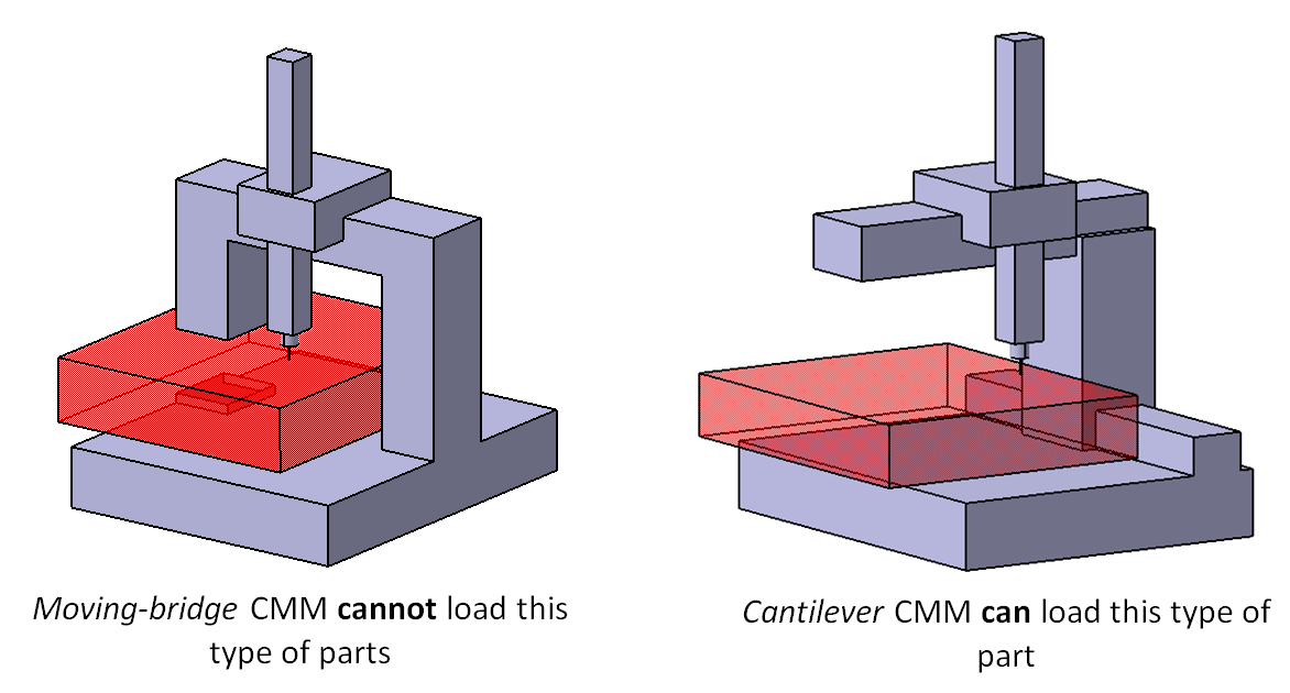
CMM configuration is very important to consider when selecting a CMM for a specific application. Figure 3 shows how important a CMM configuration for part measurement is.
In figure 3, we can observe that the CMM configuration can be a significant factor to determine the flexibility of part measurements.
In figure 3 right, a cantilever CMM can have a higher flexibility compared to moving- or fixed-bridge CMM. Because, the cantilever CMM can accommodate larger part than a bridge-CMM can. However, the cantilever CMM will have a lower accuracy than a bridge-CMM.
That is why, cantilever CMM is very suitable to be used for automatic car body measurement. Because the CMM arm can access feature that is quite far with respect to a CMM reference point.
- Measured part’s weight
Every CMM has its own maximum part weight capacity that it can hold. If the part weight exceed the CMM maximum load capacity, there will be a deformation induced to the CMM structure, may be only at micro-metre or millimetre scale.
This small deformation will significantly contribute to CMM measurement errors. In the worst case, the structure of the CMM will have a permanent deformation on it structure.
Because the deformation is in micrometre and millimetre scale, the deformation will be difficult to notice and the CMM accuracy reduces significantly.
- Measuring speed
There are various measure of CMM measurement speed: measurement speed, acceleration speed and deceleration speed. The most common parameter is the measurement speed.
There are two main mode or method for CMM measurement mode: point-by-point and scanning mode. Figure 4 below shows the example of point-by-point and scanning measurement modes.
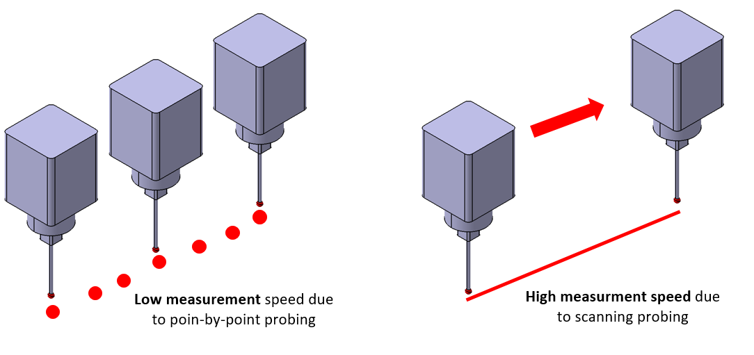
For point-by-point measurement mode, measurement speed will be low, but the accuracy of the point will be high. On the other hand, for scanning mode, the measurement speed will be high, but the accuracy of the points will be low because of errors coming from the high dynamic of CMM scanning movement.
A key take away related to measurement speed is that to perform measurement speed comparison with a reference (for example, a CMM supplier) to evaluate the measurement time, to evaluate the time required to probe a single point (including the acceleration and deceleration speed), to evaluate the CMM speed for a large part to estimate the time required by the CMM to move from one position to another far position.
- Probing (sensor) type
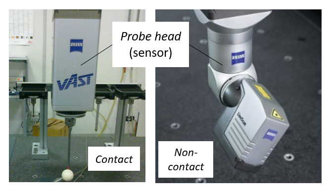
Probing is a part of a CMM that sense the spatial coordinate in the surface of a measured part either by physically touching the surface of optically (non-contact) sense the surface.
Figure 5 below shows examples of tactile probing and optical-probing system of a CMM. As shown in figure 5, the tactile probing system has a spherical tip (commonly made of ruby) that will touch a surface. Meanwhile, the optical probing has at least one camera and light source (for example laser source) to bounce lights on a surface and capture the reflected light form the surface to reconstruct the spatial coordinate of a surface.
Tactile probing system has a lower throughput compared to optical probing system. However, the tactile probing system has a higher accuracy compared to the optical probing system.
Tactile (contact) probing has some drawbacks, such as it will create a damage when it is used to measure a soft surface. For example, a highly deformed sheet-metal surface can be dented when the surface is touched by a tactile probe. Also, tactile probing system has a limited access to small features on a part.
Meanwhile, optical probing can be used to measure soft surfaces without worry to damage the surfaces. Commonly, an optical probing mounted on a Cartesian CMM uses a laser-scanning head. This laser-laser scanning head has a relatively big laser spot of around 0.2 mm so that this big spot limit the capability to measure small features.
In addition, optical probing cannot measure a vertical surface or surface with very high slope angle (such as > 80 degree). Because, for vertical surface, the reflected light from a surface cannot return back to the sensor (imaging sensor or photo-detector) of an optical probing system.
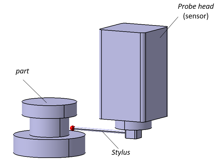
Meanwhile, tactile probing can measure a vertical surface. Figure 6 below shows an example of tactile probing system that is used to measure a vertical surface of a cylinder by using a horisontal stylus configuration.
The software ability of CMMs
The main software abilities of a CMM to be considered when selecting a CMM are the CMM programming method, user interface, data evaluation system, data interface and data output format.
The explanation of those software abilities are as follows.
- The CMM programming method
One of the main advantage of a modern CNC-equipped CMM is that the CMM can be programmed to run automatically for various type of measurement motions. With this automation, automated CMM can reduce measurement cost up to half of the measurement with manual CMMs.
In addition, automated CMMs have a more consistent results since the effect from an operator can be eliminated. A programmed CMM can automatically touch the same target repeatedly in a range of (0.005-0.05) mm, depending on the measurement, acceleration and deceleration speed. As a comparison, a manual CMM commonly have a repeatability to touch the same target in a range of 5 mm, depending on the skill of an operator.
There are three main methods to program a CNC-equipped CMM:
- Teaching-based programming. This method is performed by manually touch the point location on a surface to measure and the CMM controller will record the point location and the motion pattern so that the CMM can measure automatically following the recorded point locations.
- Parametric-based programming. This method is based on the similarity level of a measured part with another part. This method is based on teaching-based programming and the slightly modify to accommodate other part measurements with a slight shape difference.
- Off-line programming. This programming method is based on the computer-aided design (CAD) model of a part to measure. From a CAD model, features on a part can be determined. In addition, the location and size of the features can be determined from the CAD model. By using the CAD model, a manual teaching is not needed. Also, by having the CAD model, the results from a measurement can be directly compared to the CAD model so that the deviation of the part from its nominal dimensions can be calculated.
- User interface
There are various CMM software available due to many CMM manufactures, such as Zeiss, Mitutoyo, Leitz, Brawn and sharpe, DEA and other manufacturers. In addition, there are several universal CMM software that can be used for different types of CMM machines.
The above situation causes there are many different type of software interface. Hence, the consideration on how easy and intuitive the user interface of a CMM software is very important. The shorter the learning time of a CMM software by an operator, the less the training cost will be needed.
- Data evaluation system
The main data evaluation capability of a CMM software is to process a 3D point cloud obtained from a measurement and perform a geometrical fitting to perform dimensional and geometrical measurements, for example diameter, flatness, height and hole location measurements.
The basic CMM data evaluation capability is to perform basic geometrical fittings, such as circle, plane, conic, cylinder, sphere and ellipse fitting.
The fitting process can be done by several methods, such as least-square fitting, maximum inscribe fitting, minimum circumscribe fitting and free-form fitting with NURBS method. The CMM algorithm should be tested with a reference data to test the correctness of the algorithm.
- Data interface
Data interface is how the measurement results of a CMM can be transferred for other needs to another software. The purposes of the data transfer are for example to perform statistical analysis from the measurement data, to compared to a CAD model and to analyse data for decision making process.
- Data output format
There are various type of data output format for CMMs. The basic format of the output is a text file containing x,y,z, locations of obtained points as well as the approaching vector of a tactile probing. Nowadays, most of modern CMMs can produce data output in a specific and adjustable report format.
The sampling strategy capability of CMMs
Sampling strategy is defined as the way to collect a point cloud (spatial data points) from a surface.
Measurement results from a CMM are obtained by deriving dimensions from a fitted or associated geometry to obtained 3D spatial point clouds. To obtain these point clouds, there are different sampling strategy to capture or probe the points.
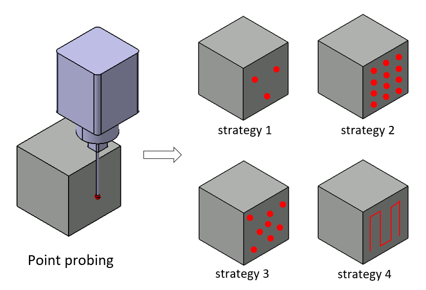
Figure 7 above shows examples of different sampling strategies to measure flatness on the same surface of a cube. In figure 7, the strategies are ranging from minimum three points sampling, grid sampling, random sampling and line sampling with scanning mode.
Different sampling strategies will have different accuracy as different sampling strategies involve different dynamics of the motion of a CMM. The number of sampling points significantly affect a measurement results, for example, for a diameter measurement, if the sampling only cover a small number of points at a specific location of the arc of a circle, it will cause a large diameter measurement error.
Other aspects to consider
Other aspects that need to consider when selecting a CMM are the time required to train a new CMM operator, fixturing systems, environment condition, warranty and after-sale support from a CMM manufacturer and sub-contracting CMM measurement.
- Required training time for a new operator
Operating a CMM machine is a complex task. The consequence is that a long training time will be required to teach a new CMM operator to a level that the operator can correctly operate a CMM machine and can provide a good measurement result.
This training time should be viewed as an investment not as a cost centre. Because, by having a skilled CMM operator, the operator can generate good measurement results and data so that good decisions can be made. In addition, a good CMM operator can optimise a measurement task to be very efficient.
- Fixturing system
Every CMM manufacturer provides their own fixturing system. Fixtures are very important to be able to hold part properly for measurement. The main function of fixturing system is to be able to repeatedly locate, orient, and hold a part for measurement properly.
- Environment condition
The environment where a CMM will be placed is very important. A CMM that will be placed in a controlled laboratory will have a different specification with another CMM that will be placed in a shop floor.
CMMs equipped with air bearing systems are only suitable for use in a controlled laboratory. Because, air bearing is very sensitive to temperature variation, but with air bearing CMM motions can be smooth and fast.
For shop floor, most CMMs use ball bearing systems in their motion axes to be robust to temperature variation. However, the motion axis will have a low speed.
- Warranty and after-sales service
CMM warranty and after-sales service are also important. Because, CMM is a very sensitive and complex. Any problems found in a CMM should be fixed within short time to not stop or delay production process at a quality inspection station.
- Sub-contracting CMM measurement
CMM is very expensive. For an example, the common price for a moving-bridge CMM is about £250k. Hence, if the volume of measurements is low and skilled operators are lacking, maybe the best way is not to but our won CMM, instead, we can sub-contract our CMM measurement tasks to another company.
General applications for CMM
Very often, CMMs are used to be considered as “cost centre” in industry. Because, CMMs are not production machines that can create physical parts to be sold for profit.
However, in reality, CMMs are a “profit centre” if they are applied correctly and efficiently.
With CMMs, various shapes of parts or components can be measured to inspect the quality of the parts and subsequently, to maintain the quality. By producing high quality products, a company can compete in the market and sell many products with high customer satisfaction (small after-sales service cost).
In addition, CMMs can be used to measure parts after production processes to investigate and improve the production processes. By the improvement, the production processes can produce parts at lower cost, high speed and high quality, causing a low production cost and a large profit margin per each product sale.
CMMs can be used from a very simple measurement, such as a diameter and length measurement, to a very complex measurements, such as free-form part measurements, automotive engine measurements, the centre of a cooling hole on a jet propulsion aerofoils, gear measurement, metal die casting measurement, large turbine measurement at > 10 m scale, and the turbine of a jet propulsion engine measurement.
In addition, high-accuracy tactile CMMs, such as moving-bridge and fixed-bridge CMMs are very common to be used to calibrate an artefact used for reference for other measuring instruments.
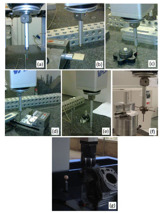
Figure 8 below shows some examples of various dimensional and geometrical measurements performed by using a CMM. The measurements shown are from a simple diameter measurement to a complex engine block measurement.
Conclusion
In this post, the introduction of CMMs, including various classifications of them, has been presented. In addition, important aspects that need to be considered to select a CMM for a specific needs are explained in details.
The fundamental difference between tactile (contact) CMM and optical (non-contact) CMM in term of measurement modelling is also given.
Finally, some examples of general measurement applications of CMMs are presented. In these examples, various types of dimensional and geometrical measurements of parts with various shapes are shown.
From this post, readers can have a general understanding of CMMs, their function and types, and most importantly, readers know how to consider when selecting a CMM for their applications.
We sell all the source files, EXE file, include and LIB files as well as documentation of ellipse fitting by using C/C++, Qt framework, Eigen and OpenCV libraries in this link.
We sell tutorials (containing PDF files, MATLAB scripts and CAD files) about 3D tolerance stack-up analysis based on statistical method (Monte-Carlo/MC Simulation).