Examples on how to interpret GD&T: Form, orientation, location and run-out tolerances
This post presents and discusses real examples on how to interpret GD&T tolerancing symbols from technical drawings.

This post presents and discusses real examples on how to interpret GD&T tolerancing symbols from technical drawings.
By reading this post, you will understand how to read and interpret GD&T symbols from any drawings. The understanding of interpreting GD&T is instrumental to understand and perform 3D tolerance stack-up analyses (and also 2D tolerance analyses).
In essence, tolerance stack-up analysis is a translation of GD&T symbols in technical drawings into variation transformation chains. From these variation chains, the variation of the key characteristics of assemblies, accumulated from the assemblies’ component variations, can be predicted even before the manufacturing of the components and the assembly processes are carried out.
Form tolerance examples include straightness, line profile and surface profile, flatness, roundness (circularity) and cylindricity.
Orientation tolerance examples include squareness/perpendicularity, parallelism and angularity.
Location tolerance examples include symmetry, concentricity and position.
Run-out tolerance examples include only profile run-out.
Finally, an example of multiple combination of GD&T in one part is also given as the last example in this post.
It is important to note that GD&T tolerance is also knows as geometrical tolerance.
The most well-known measuring machine for GD&T verification is coordinate measuring machine (CMM).
If you want more details and interesting 3D tolerance stack up analysis, we sell tutorials (containing PDF files, MATLAB scripts and CAD files) about 3D tolerance stack-up analysis based on statistical method (Monte-Carlo/MC Simulation). You can purchase from the given link.
Do you want to have good research philosophies and improve your research management and productivity?
This book is a humble effort to map well-known and proven principles and rules from various disciplines, such as management, organization decision theory, leadership, strategy, finance and marketing, into a single practical research guide that applies to all disciplines.
The book’s chapters cover: How do you determine the primary research tools? How do you select research philosophies? How do you make research strategies? How do you determine research innovation? How do you navigate complex research? How do you economically justify research? How do you economically value research? How do you manage research? How do you market research?
The synopsis of this book can be found here.
You can also get this book from Rakuten Kobo.

READ MORE: Tactile CMM: The reference of dimensional and geometrical measuring machine in industry.

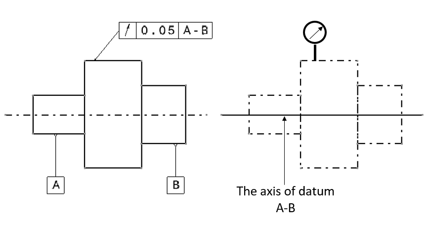
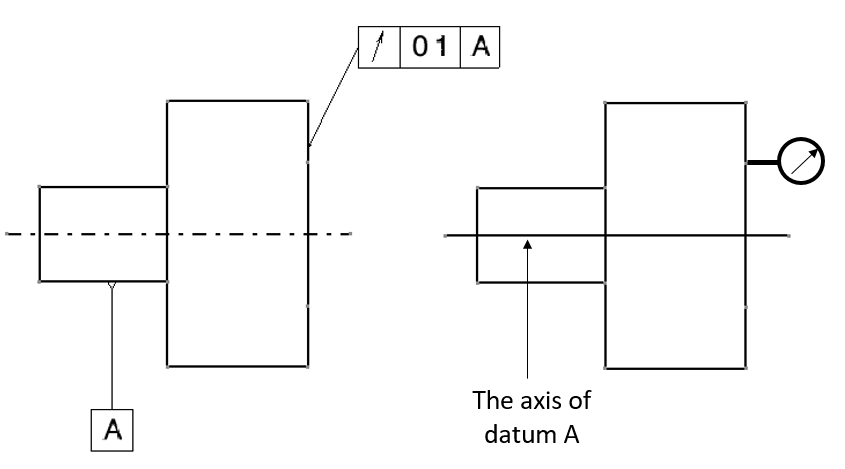
Squareness
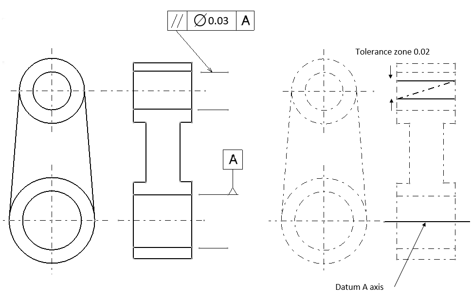
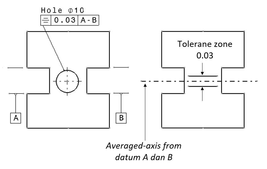
In this example, there are two squareness examples. Figure 1 and figure 2 show the example of the squareness of an axis (line) with regards to a datum axis and the example of the squareness of a surface with respect to a datum axis, respectively.
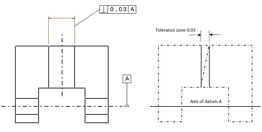
The reading and interpretation of the example in figure 1 above is as follow. The axis of the pointed vertical hole should lie within its tolerance zone. This tolerance zone is two hypothetical parallel planes that are separated for 0.03 (unit distance) and these parallel planes are perpendicular with respect to the axis of datum A.
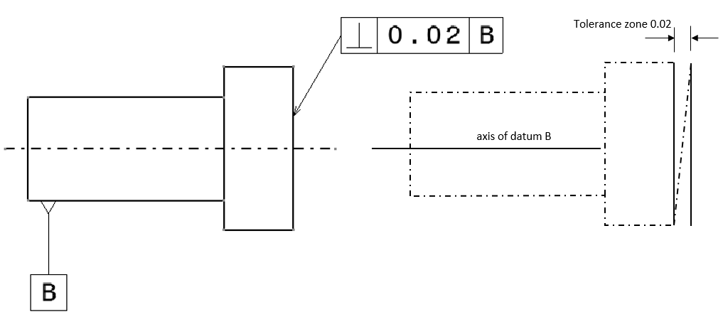
The reading and interpretation of the example in figure 2 above is as follow. The pointed cylinder surface should lie within its tolerance zone. This tolerance zone is defined as two hypothetical parallel planes that are separated for 0.02 (unit distance) and are perpendicular with respect to the axis of datum B.
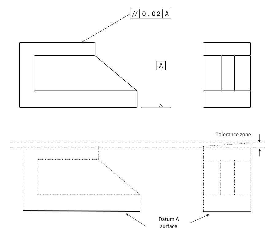
Parallelism
Examples of parallelism are shown in figure 3 and figure 4. In figure 3 below, the example of the parallelism of a surface with respect to a datum surface is shown. The interpretation of the parallelism tolerance in figure 3 is as follow.
The pointed surface should lie within a tolerance zone that is two parallel planes that are separated for 0.02 and are parallel with respect to the surface of datum A.
In figure 4 below, the example of the parallelism of an axis with respect to a datum axis is presented. The parallelism interpretation of figure 4 is as follow.
The axis of the pointed hole should lie within a tolerance zone that has a cylindrical shape with diameter of 0.03 (unit distance). The cylindrical tolerance zone should be perpendicular with respect to the axis of datum A.
From the two examples of parallelism tolerance, there are various types of parallelism. For example, a parallelism between an axis and a surface, between a surface with another surface and between one axis with another axis. These various types of situations are also found in other types of GD&T tolerance.
Line profile
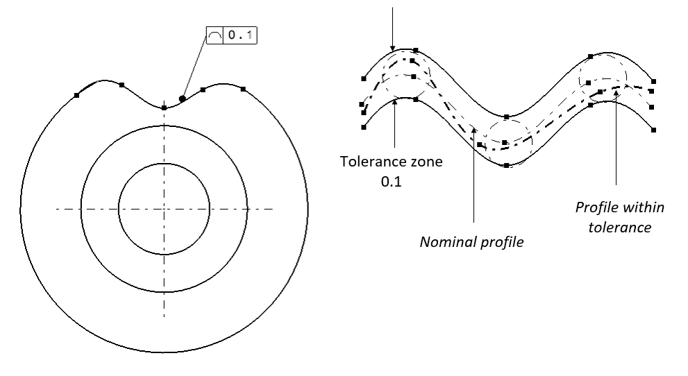
Figure 5 below shows the example of the line profile tolerance of a curve on a part. The geometrical interpretation from the technical drawing in figure 5 is as follow.
The pointed line profile on the drawing should lie within a tolerance zone. This tolerance zone is two line profiles that are equally separated on each point in the line for 0.1 (unit distance).
Line profile is a non-related tolerance. That is, this type of tolerance does not need a datum definition (similar to flatness, roundness or circularity and cylindricity tolerance).
Surface profile
The example of a surface profile tolerancing on a part with curve-surface is presented in figure 6. In figure 6, the reading and interpretation of the surface profile tolerance is as follow. The pointed surface on the part should be within a tolerance zone. This tolerance zone is defined as two curved surfaces (identical to the nominal curve surface of the part) that are separated equally at any point on the surface (parallel) with a distance of 0.02 (unit distance).
Since this tolerance is a type of form tolerance (such as flatness, straightness, roundness or circularity and cylindricity), this surface profile tolerance does not require any datum (un-related tolerance).
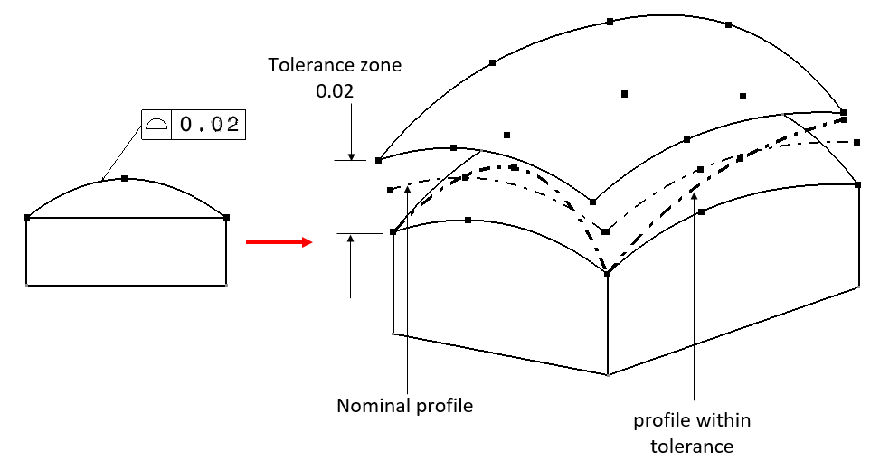
One important thing to know is that, because the shape of the surface is curved, the measurement process (which commonly performed by using a coordinate measuring machine/CMM) to measure the curved surface and verify the tolerance is significantly affected by how many measurement points taken from the surface. The sampling strategy of the measurement should be good enough to be able to accurately reconstruct the curved surface and extract the measurement result.
Symmetry
There are two symmetry tolerance examples that are shown in figure 7 and figure 8. In figure 7, the example of symmetry tolerance of an axis with respect to a datum axis is presented.
The symmetry tolerance interpretation in figure 7 below is as follow. The pointed axis should be within two parallel lines that are separated each other for 0.08 (unit distance). These parallel lines should contain the averaged-axis line from datum A and datum B. This averaged-line should be at the middle between the two parallel lines.
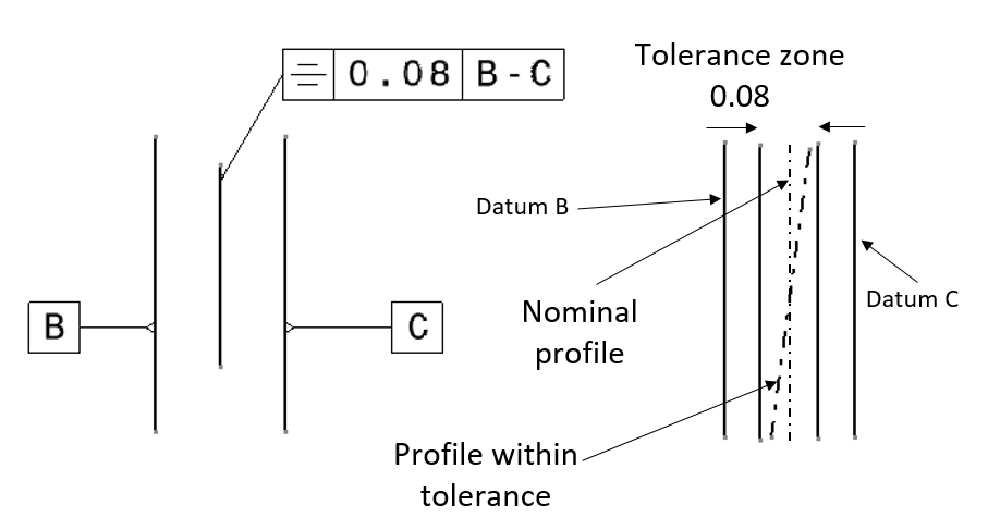
Figure 8 below presents the example of symmetry tolerance of an axis with respect to an averaged-axis from two datum.
The interpretation of symmetry in figure 8 is as follow. The pointed axis should be within two parallel lines that are separated each other for 0.03 (unit distance). These two parallel lines should contain an averaged-line from the axis of datum A and datum B at the middle.
Concentricity
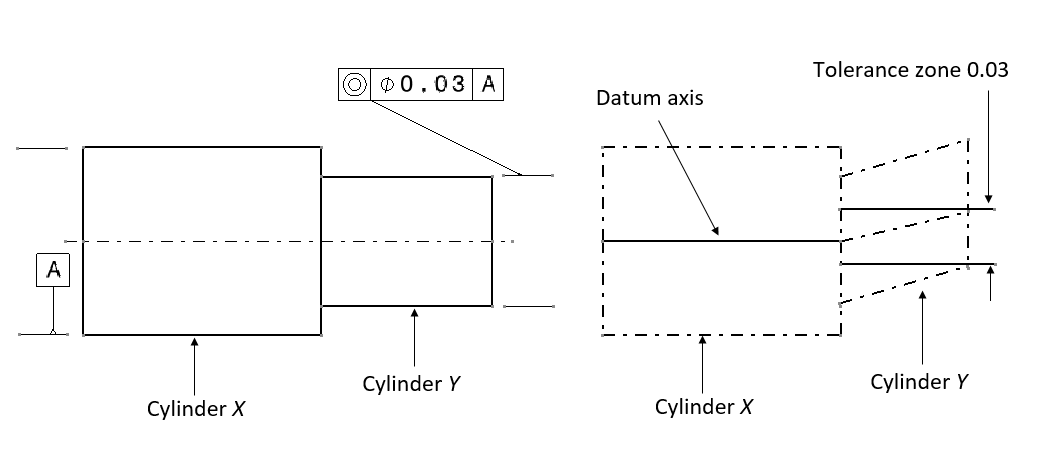
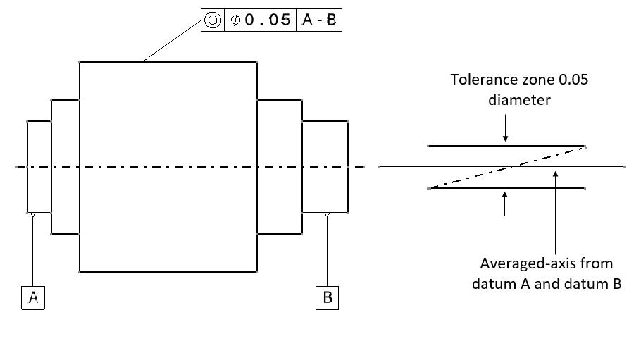
Figure 9 and 10 below shows the example of concentricity of an axis with respect to a datum axis and with respect to an averaged-axis from two datum A-B, respectively.
The interpretation of concentricity in figure 9 below is as follow. The axis of the pointed cylinder in the technical drawing should be within a tolerance zone in a form of cylinder with diameter of 0.03 (unit distance). The axis of the cylindrical tolerance zone should be co-axial with the axis of datum A cylinder.
Meanwhile, the interpretation of concentricity in figure 10 below is as follow. The axis of the pointed cylinder in the drawing (figure 10) should be within a tolerance zone. This tolerance zone should be a cylinder with a diameter of 0.05 (unit distance) and is co-axial with the averaged-axis of datum A cylinder and datum B cylinder.
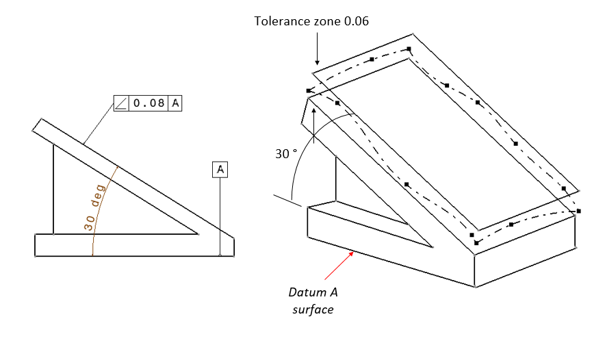
Angularity
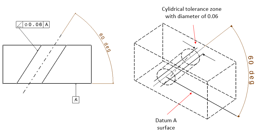
There are two examples of angularity tolerance shown in figure 11 and figure 12 below. In figure 11, angularity of an axis is presented. Meanwhile in figure 12, angularity of a surface plane is presented.
The interpretation of angularity tolerance in figure 11 is as follow. The axis of the pointed hole in the drawing should be within a cylindrical tolerance zone with a diameter of 0.06 (unit distance). The axis of this cylindrical tolerance zone should has orientation of 60 degree with respect to the surface of datum A.
Meanwhile, the interpretation of angularity in figure 12 below is as follow. The pointed surface on the technical drawing should be within a tolerance zone. This tolerance zone is two parallel planes that are separated for 0.08 (unit distance). These two parallel planes should be oriented for 30 degree with respect to datum A surface shown in the drawing (figure 12).
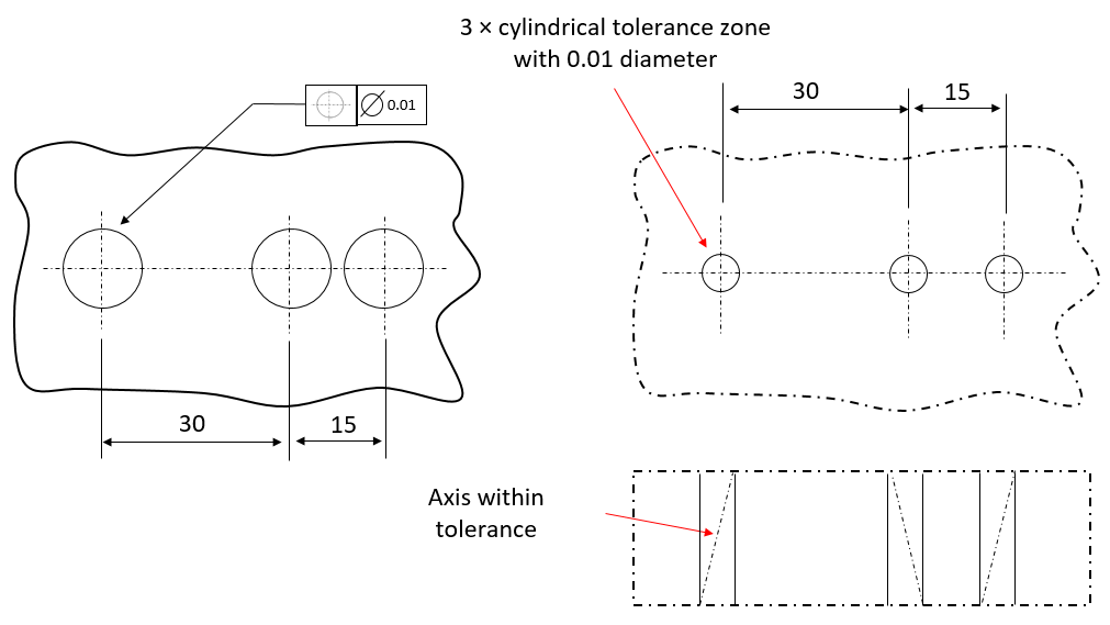
Position
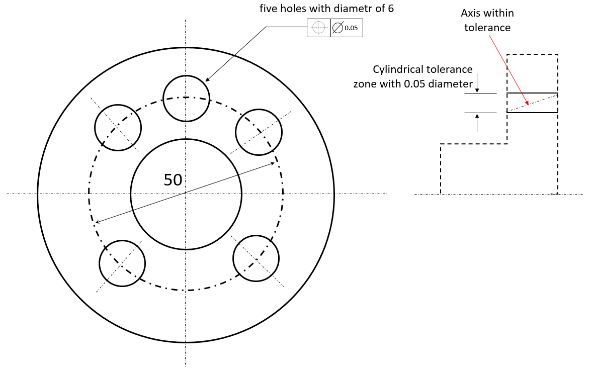
Figure 13 and figure 14 below shows the examples of position tolerance of an axis with respect to other two axes and with respect to a cylinder axis, respectively.
The explanation of position tolerance in figure 13 is as follow. The axis of the pointed hole should be within a cylindrical tolerance zone with diameter of 0.01 (unit distance). The axis distance of this cylindrical tolerance zone should be 30 (unit distance) with respect to the first cylinder and 45 (unit distance) with respect to the second cylinder (figure 13 right). In addition, the axis of the cylindrical tolerance zone should be parallel with the axis of the other two cylinders (holes).
The explanation of position tolerance in figure 14 is as follow. The axis of the pointed hole should be within a tolerance zone. This tolerance zone has a cylindrical shape with diameter of 0.05 (unit distance). Also, the axis of the cylindrical tolerance zone should have a distance of 50/2=25 (unit distance) from the axis of the main (the biggest) cylinder (figure 14 left).
Specifically for position (or location) tolerance, although its symbol in a technical drawing does not refer to a datum, inherently, position/location tolerance symbol refer to a datum. That is why, for clarity, in general, position/location tolerance symbol in a technical drawing also shows a reference datum.
Straightness
Examples of straightness on the same part, but with different tolerance conditions are presented in figure 15 below.
In figure 15a below, the example of straightness of the pointed cylindrical surface and not the axis of the cylinder. The interpretation of this straightness is as follow. The profile of the pointed surface should be within a tolerance zone of two parallel lines separated for 0.03 unit distance. The measurement for this tolerance is by taking points of profile lines by a CMM or other measuring instruments.
In figure 15b below, the example shows the straightness of the pointed axis of the small cylinder. The reading of this straightness tolerance is as follow. The axis of the pointed small cylinder should be within a tolerance zone that is two parallel lines separated for 0.03. In addition, the length of this tolerance zone follows the length of the small cylinder only (not including the big cylinder).
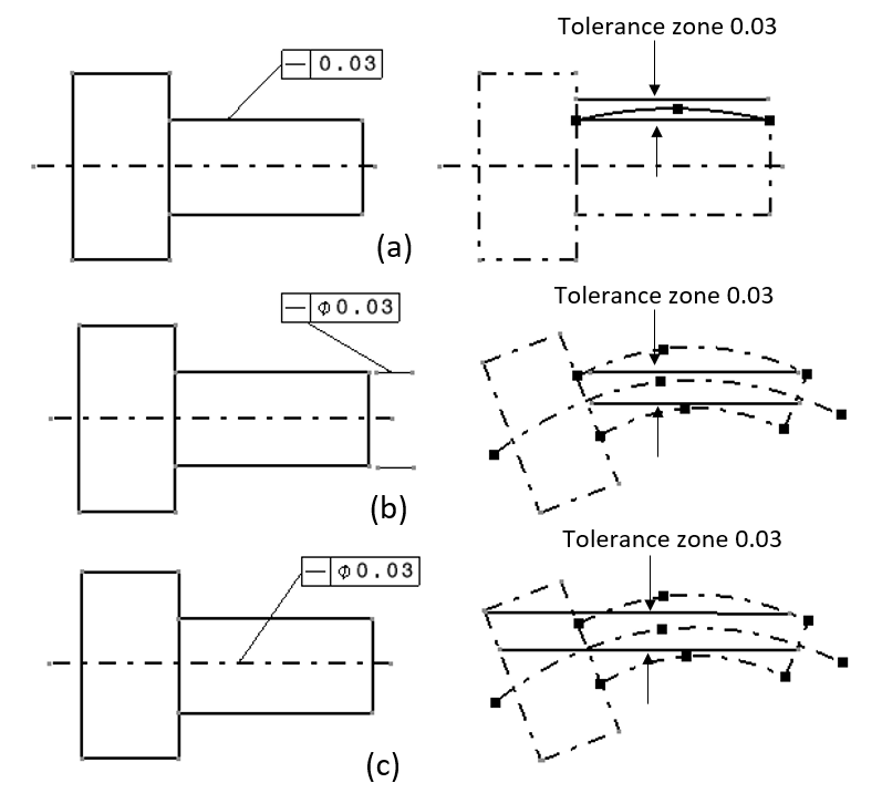
In figure 15c above, the example shows the straightness of an axis with respect to the whole length of the cylinder, including both the small and big cylinders. The interpretation of the straightness tolerance in figure 15c above is as follows. The whole axis of the cylinder (both the small and the big one) should be within a tolerance zone. This tolerance zone is in the form of two parallel lines that are separated for 0.03 unit distance and the length of this tolerance zone (the two parallel lines) covers the whole length of the cylinder (both the small and the big one).
Run-out
Two examples of run-out tolerance are shown in figure 16 and figure 17 below.
In figure 16 below, the run-out tolerance requires all the cylinders should satisfy their roundness, concentricity and parallelism tolerances for the pointed cylindrical surface.
The interpretation of the run-out tolerance in figure 16 above is as follow. For every section of the pointed cylinder (the big cylinder in the middle), the total movement of the indicator pointer of the dial-gauge should be less than 0.05 when the cylinder is rotated for full 360 degree rotation.
In figure 17 above, the run-out tolerance requires all the cylinders should satisfy their squareness and flatness tolerances for the pointed flat surface.
The interpretation of the run-out tolerance in figure 17 above is as follow. For any points located at any radius on the plane from the centre point of the pointed surface, the total movement of the indicator pointer of the dial-gauge should be less than 0.1 when the cylinder is 360 degree rotated.
From the two run-out examples above, it can be observed that run-out tolerance indirectly also cover other GD&T tolerances as well (depending on what feature the run-out tolerance is applied to).
GD&T combination
In this example, the example of a GD&T tolerance combination of a shaft with various different features is presented.
In real condition, even a single component will have different features and a single feature can have one or more GD&T tolerances. This example shows one of real case studies of a single shaft component with multiple features.
Figure 18 below shows the 3D drawing of the shaft component. In figure 18, it can be observed that the shaft has multiple cylindrical features with different diameters, multiple holes on the surface of one of the cylinder and a slot feature (keyway) at one of the end of the shaft with the smallest diameter.
Each cylindrical feature on the shaft has their own important functionality. Also for the hole features, they contribute to a specific functionality to the shaft.
The geometrical features on the shaft are related to each other. To represent these relations, GD&T or geometrical tolerance should be used to represent the relations by complementing the traditional dimensional tolerance.
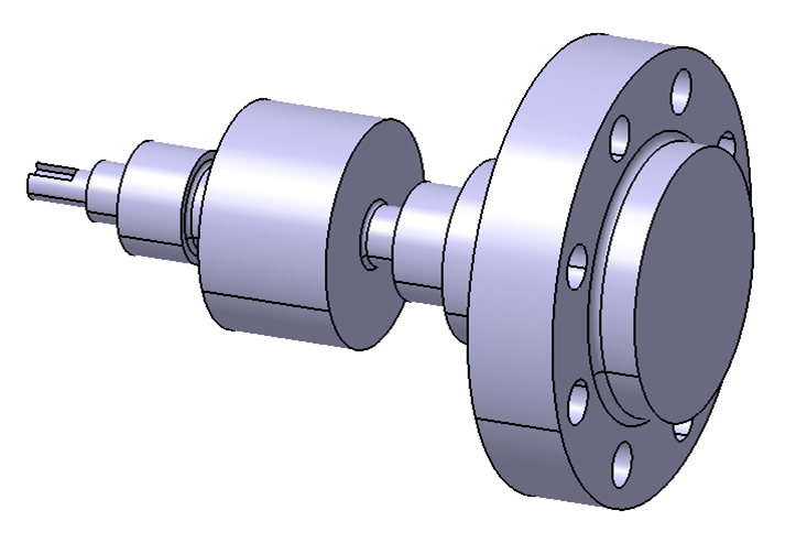
Figure 19 below shows the 2D technical drawing of the shaft. From this 2D drawing (technical drawing), all the types (tolerance symbols) and values of dimensional and GD&T tolerances are presented.
In figure 19, only the GD&T tolerances of the features on the shaft are presented. Also, for dimensional tolerances, only those tolerances that are related to define the GD&T tolerances of the features are shown.
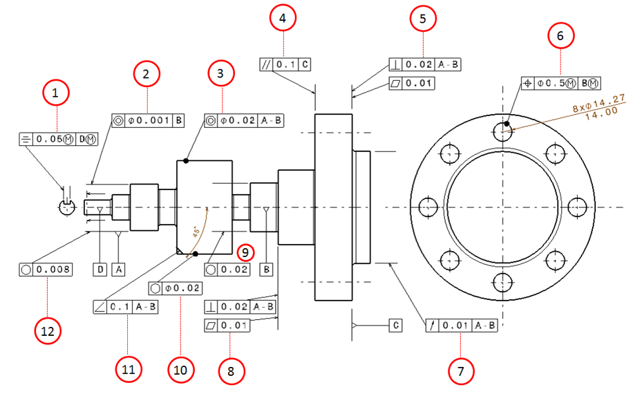
The explanation of the meaning and interpretation of all the tolerances in this shaft component example (figure 19 above) is explained as follow.
Explanation of for each GD&T tolerance symbols (figure 19 to follow the number annotations):
1. Symmetry
The flat surface that lies in the middle of the slot (keyway) should be within two parallel planes separated for 0.05 unit distance. The two parallel planes are symmetry with respect to the axis of datum D when the shaft and the slot (keyway) are manufactured at their maximum material condition (MMC). This tolerance is a type of location tolerance.
2. Concentricity
The axis of the pointed cylinder datum should be within a cylindrical tolerance zone with diameter of 0.01 unit distance. The axis of the tolerance zone should be coaxial with the axis of datum B.
3. Concentricity
The axis of the pointed cylinder datum should be within a cylindrical tolerance zone with diameter of 0.02 unit distance. The axis of the tolerance zone should be concentric with respect to the averaged-axis of datum A-B.
4. Parallelism
The pointed flange surface should be within a tolerance zone of two parallel planes. These two parallel planes are separated for 0.1 unit distance. Also, the parallel planes should be parallel to the surface of datum C.
5. Perpendicularity and flatness
The pointed surface should be within a tolerance zone of two parallel planes separated from each other for 0.02 unit distance. The parallel planes should be perpendicular to the axis of datum A-B. Also, the pointed surface should also within another tolerance zone of two parallel planes separated from each other for 0.01 unit distance.
6. Location
The centre for each hole should be within a cylindrical tolerance zone with diameter of 0.5. The diameter of this cylindrical tolerance zone can increase if there is a variation on the MMC of the holes and on the diameter of datum B cylinder feature.
7. Circular run-out
When this feature is rotated for full 360 degree rotation and is checked by a dial-gauge with respect to the axis of datum B, the maximum movement on the pointer indicator of the dial-gauge, at any points on the pointed surface, should be less than 0.01 unit distance.
8. Perpendicularity and flatness
The pointed surface should be within a tolerance zone. This tolerance zone is defined as two parallel planes that are separated from each other for 0.02 unit distance and are perpendicular to the axis of datum A-B. Also, the pointed surface should be within another tolerance zone of two parallel planes separated for 0.01 unit distance.
9. Roundness (circularity)
The pointed bearing surface should be within a tolerance zone that is defined as two concentric circles. These two concentric circles are radially separated for 0.08 for all section plane of the feature that are perpendicular to the axis of the pointed bearing surface.
10. Roundness (circularity)
The pointed surface should be within a tolerance zone of two concentric circles separated for 0.02 unit distance. These concentric circles should lie on all section plane taken perpendicularly with respect to the axis of the pointed cylinder.
11. Angularity
The pointed surface should be within a tolerance zone of two parallel planes that are separated for 0.1 unit distance. These two parallel planes should be 45 degree oriented with respect to the axis of datum A-B.
12. Roundness (circularity)
The pointed bearing surface should lie within a tolerance zone of two concentric circles. These two circles are radially separated for 0.08 unit distance. Also, the circles should be on each section plane taken perpendicularly with respect to the axis of the bearing surface.
From the above explanations of the GD&T tolerance on the shaft, it can be observed that GD&T (geometrical) tolerance has a deep meaning and interpretation. GD&T tolerance has the capability to represent the design intent from a mechanical design engineer, who has designed a component, to a manufacturer and quality inspection engineer, so that the designed component can be assembled with other components to form a working assembly with a specific functionality.
Conclusion
This post presents various types of GD&T or geometric tolerances in term of symbols on technical drawings and their interpretations.
Although the presented examples do not show all types GD&T tolerances, this post gives a significant examples that can be used to deeply understand and interpret other GD&T symbols (not presented in this post).
One important note is that GD&T is not replacing or eliminating dimensional tolerance. However, GD&T complements dimensional tolerance so that any design intent on technical drawings can be represented clearly.
You may find some interesting items by shopping here.
We sell tutorials (containing PDF files, MATLAB scripts and CAD files) about 3D tolerance stack-up analysis based on statistical method (Monte-Carlo/MC Simulation).

The synopsis of this book can be found here.