Tactile CMM: The reference of dimensional and geometrical measuring machine in industry
Coordinate measuring machine (CMM), especially tactile CMM, is the industry standard for dimensional and geometrical measurement. The use and application of CMM in manufacturing industry, from automotive, aerospace until space industry, have been matured and well-accepted.
Coordinate measuring machine (CMM), especially tactile CMM, is the industry standard for dimensional and geometrical measurement. The use and application of CMM in manufacturing industry, from automotive, aerospace until space industry, have been matured and well-accepted.
Hence, it is important to know and understand CMMs. Tactile CMM is a type of CMM that uses a stylus tip to mechanically touch the surface of a part to be measured.
This tactile CMM is the reference for other CMMs, for example non-contact (optical) CMM.
Why tactile CMM is a reference?
Because, the measurement process (including the measurement model) of tactile CMM is already well understood!
The measurement process of tactile CMM can be analytically modelled by modelling a ball rolled on top a surface (scanning mode) or a ball touching a surface (point-by-point mode). The mathematical models of these phenomena have been established and well-understood.
By having the mathematical models of tactile CMM measurement processes, we can analytically predict what data we will get from tactile CMM measurements and can compare with our real measurements. By this comparison we can estimate and understand the error of our measurements and have confidence on the measurement results.
READ MORE: Coordinate measuring machine (CMM): An introduction, types, considerations and applications.
Cartesian tactile CMM
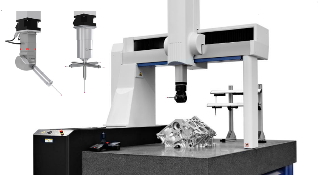
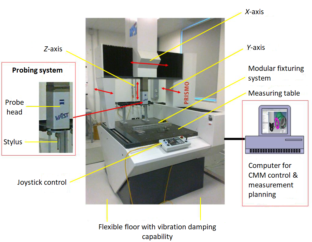
The basic construction of tactile CMM, regardless what configuration the CMM is, is shown in figure 1. In figure 1, the shown tactile CMM has a moving-bridge structure. This structure is the most common type of tactile CMM used in industries and laboratories.
Fundamentally, there three main parts of a tactile CMM construction: mechanical structure, probing system (sensor), computer and controller system.
Whatever the types of tactile CMM are, they will be constituted by these three main parts.
Mechanical structure of tactile CMM
From figure 1 above, the mechanical structure of a tactile CMM includes measuring table, X-Y-Z motion axes, fixturing systems (either modular or fixed-construction) and the structural frame of the CMM.
The X-Y-Z motion axes, that is the motion system of a tactile CMM, consists of two components: motion source and motion transfer.
Motion source, in this case electric motor, consists of rotational motor and linear motor.
In general, rotational motor is suitable to be used as the motion source of a tactile CMM. Because, the rotational motor can be placed far from the motion axis of the CMM. By doing this, the heat transferred from the motor to the axes can be reduced, that is, reducing geometrical error due to thermal expansion.
Meanwhile, linear motor is always placed on the motion axes of a tactile CMM so that heat generated on the motion axes will be high (mainly contributed from the motor). In addition, linear motor will require an electrical brake mechanism when it has to stop at a certain position. This electrical block will generate significant heat on the motor and the heat will be directly transferred to the motion axes.
The advantage of using linear motor system is that this linear motor can produce high speed motion and does not need a complex drive system (gears) compared to rotational motor system.
Rotational motor system will require a drive system to transfer the rotational motion to linear motion of the axes of a tactile CMM. Types of drive systems used in rotational motion system are: rack-and-pinion, belt, friction and leadscrew drive. Leadscrew drive is the most common used drive system to transfer the rotational motion to linear motion in a rotational motor system.
Bearing system
Bearing is a vital component to construct a motion system. There are two types of bearing: contact (mechanical) bearing and non-contact (air or magnetic) bearing.
Examples of contact (mechanical) bearing are ball bearing and roller bearing. Meanwhile, examples for non-contact bearing are bearings which are based on air suspension or magnetic suspension.
To choose a correct bearing for tactile CMM, main design criteria to consider in selecting a bearing type are dynamic stiffness, load bearing capability, vibration damping and friction effect.
Air bearing uses a thin-film layer of air with a certain pressure (commonly 6 bar) to be able to suspend a certain level of load (although the load that can be suspended is not high) with no friction. The thin-film layer is commonly about (1-10) micrometre thick.
CMMs that use air bearing should be placed in a temperature-controlled laboratory. Because, the pressurised air used for the bearing will have high variation with respect to temperature changes. Air bearing systems do not require lubrication and only require controlled air pressure.
Contact (mechanical) bearing has a higher ability to suspend loads than non-contact bearing, such as air bearing. However, mechanical bearing has a significantly higher friction than non-contact bearing. This high friction will generate heat that will be affecting the expansion of a CMM structure.
To minimised heat generated form mechanical bearings, the motion speed on an axis that uses mechanical bearings should be set low.
Since mechanical bearing has a minimum effect to temperature variation, CMMs that use mechanical bearing are commonly designed to be placed in shop floors. For maintenance, mechanical bearings require lubrications.
Encoder system
The sensor system (displacement transducer) used to measure the motion of an axis is also a vital component of CMM. Because, with the displacement transducer system, the spatial coordinate or position of the stylus (after sensing/probing a surface) of a CMM can be determined.
There are several components constructing the sensor system (displacement transducer) to read axis motion: linear encoder, rotation encoder, inductosysns, magnetic scale and laser interferometer.
The most used motion sensors are linear encoder, rotation encoder (for CMM that has rotational axes) and laser interferometer.
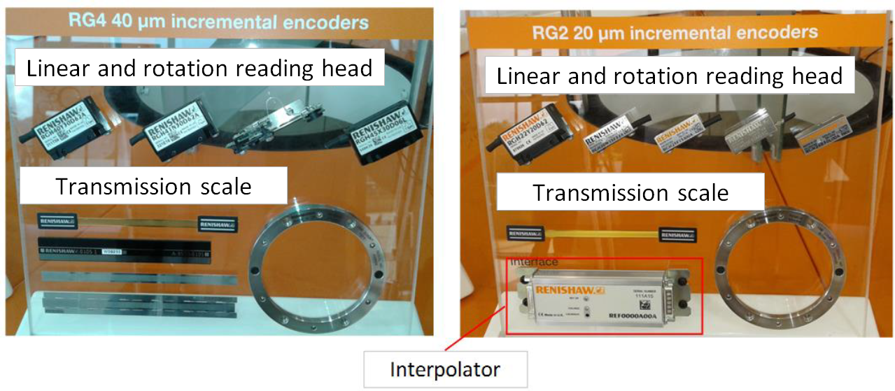
For both linear and rotation encoder, there are main components constituting the encoders that are transmission scale and reading head (used to read the scale on the transmission scale). There are several types of transmission scale and reading head system, that are photo-transmission scale (very common), reflection scale, interferential scale and laser interferometer scale.
Figure 2 below shows some examples of encoder system. In figure 2, there are two types of encoder: encoder with 20 micrometre and with 40 micrometre pitch. This pitch distance is the physical lines or grating on the scale.
Due to the pitch scale is in micrometre scale, hence, to get resolution up to nanometre scale, an interpolator is required that divide the scale pitch into smaller divisions. For example, an interpolator with 1000 divisions on an encoder with 20 micrometre pitch scale will produce a resolution reading about 20/1000 = 20 nanometre level.
Measurement table
Measurement table on CMMs is generally made of granite. Granite is a type of ceramic materials that has very low coefficient thermal expansion that causes the material to be robust with temperature variation and has a very long structural stability
There are also several types of CMM that use composite materials for measurement table. However, the use of these composite materials is still not common.
Structural frame
Structural frame is the main component to keep the whole structural construction of CMMs so that there is no deformations coming from gravity effects and from the loads of measure parts placed on the measurement table of CMMs.
The main properties required for CMM structure are dimensional stability (in both short and long period of time), high stiffness, low structural mass, high damping capability, low coefficient of thermal expansion and high thermal conductivity (to be able to release heat and distribute heat quickly and homogenously and to avoid structural deformation due to thermal stress).
In reality, it is difficult to make a CMM structure that fulfils all the above-mentioned criteria. Hence there will always be a trade-off among those criteria to design a CMM for a specific purpose.
The long-term structural stability of a CMM in various environment temperature and pressure is one of the most important aspects to satisfy. However, this structural stability also depends on low coefficient thermal expansion of a CMM.
To minimise vibration effects on a CMM, the CMM should have a high damping capability (highly effective for high frequency vibration) and, at the same time, high stiffness, especially for low frequency vibration. High stiffness will usually cause low damping capability and vice versa. Hence, stiffness and damping capability are a trade-off to be determined.
Heat sources, generated from the motor of the motion axes and frictions from the motion axes, on a CMM should be quickly dissipated out from the CMM. For this reason, the structural material of the CMM should have high thermal conductivity so that heats can be transferred rapidly from the CMM to environment.
For CMM structure, two common used materials are granite and aluminium. Aluminium has a higher coefficient thermal expansion compared to granite so that aluminium will be less robust to temperature variation compared to granite. However, aluminium also has a higher thermal conductivity than granite (aluminium=$120-167 W.m^{-1} .C^{-1}$ and granite=$1-2 W.m^{-1} .C^{-1}$) so that aluminium can dissipated heat out to environment faster than granite. CMM structures made from aluminium can rapidly reach thermal stability from environmentally high temperature variation.
READ MORE: The history and introduction of CMM: the inseparable relation between CMM and GD&T.

Probing system of tactile CMM
Probing system is a component, based on mechanical and electronic systems, of CMMs that sense or detect (probe) points on the surface of measured part.
Probing system is a unified system consisting of several components: probing head, stylus and electronic module (see figure 1 above).
The probing system will detect whether the surface of a measured part has been reached and then record the reached position on the surface into the computer memory inside the controller of a CMM used to measure the surface.
Stylus, whether contact (mechanical) based or non-contact (optical) based, is the component that interacts with the surface of a measured part.
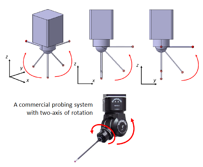
Figure 3 above shows probing systems that consist of a probing head and contact stylus, where the stylus has two rotational axes. With these additional rotational axes, a CMM that uses this type of stylus will have a total of 5-axis motion: 3-axes of linear motions and 2-axis of rotational motions.
The stylus with two rotational axes has two electrical motors on its stylus end, connected to the probing head. These two electrical motors are used to perform the two rotational motions.
With a total of 5-axis motion, the capability to access surface features of a CMM can become high. In figure 3 above (bottom), a commercial REVO contact stylus with two rotational axes from Renishaw is presented.
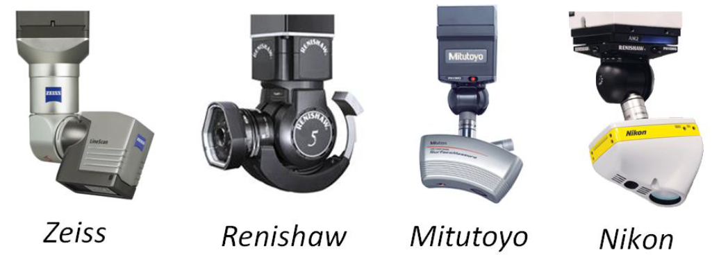
Figure 4 above shows probing systems that consist of a probing head and non-contact (optical) stylus. The optical stylus can be based on laser scanner system or vision system. Commonly, an optical stylus has the ability to rotate for different types of orientations to be able to access the features on a measured surface.
In figure 4, several commercial probing heads with optical stylus from different manufacturers are shown.
One probing head, commonly, can be used for both mechanical (contact) and optical (non-contact) stylus. However, mechanical stylus will have a better accuracy and measurement confidence than optical stylus.
Computer and controller system of tactile CMM
The control system for motion system and points on surface detections of a measured part consist of a computer and controller. The control system maintains and synchronises various components of a CMM, for example, axes motion system (drive system), displacement sensor, probing system and other components.
There are three types of level for CMM control:
- CMM with manual operation
- CMM with numerical control operation (automatic CMM)
- CMM with numerical control operation and can be connected to CAD and integrated to manufacturing system (automatic CMM)
Commonly, automatic CMM refers to type 2 and type 3 CMM as explained above.
The main function of the numerical control system of a CMM is to synchronise the motion of axes, scale reading from displacement sensors and data communication from a probing system to the controller of a CMM.
CMMs with numerical control (automatic CMM) can determine the types of sampling strategy (such as grid sampling) used to detect or probe points on the surface of a measured surface.
The sampling strategy can be point-to-point or continuous scanning.
For continuous scanning, it is divided into two types: continuous scanning with predetermined measurement parameters (speed, number of points, acceleration/deceleration and others) and adaptive scanning (speed, number of points and other parameters can change during the course of a measurement depending on surface shapes).
An automatic CMM can help operator when using the CMM, especially when identical parts are needed to be measured repetitively. With the automatic CMM, measurement programs for specific parts can be saved and used to run the same type of measurement.
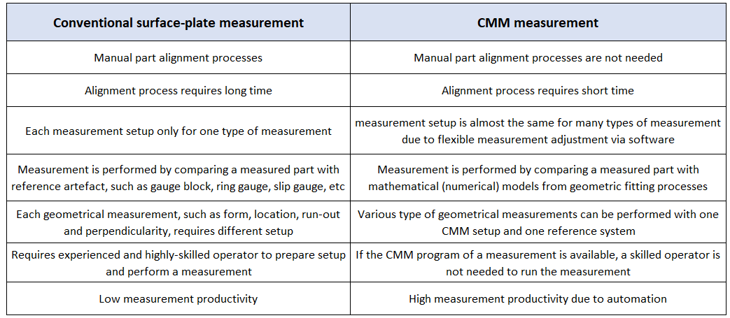
Finally, table 1 below presents advantages of using CMM for dimensional and geometrical measurement compared to using conventional surface plate system.
Conclusion
In this post, the basic structure and components of tactile CMM is presented. Tactile CMM is the most well-known and used measurement machine for dimensional and geometrical measurement.
Tactile CMM is a reference for other types of CMMs: non-contact (optical) CMM. The reason of tactile CMM is used as reference is that the measurement process of tactile CMM can be analytically modelled and has been well-understood.
Three main components of CMM have been comprehensively presented in this post: Mechanical structure, probing system and computer and controller system.
We sell tutorials (containing PDF files, MATLAB scripts and CAD files) about 3D tolerance stack-up analysis based on statistical method (Monte-Carlo/MC Simulation).