The probing system of tactile-CMM: The history, configuration and mechanism
Probing system in a tactile coordinate measuring machine (tactile-CMM) is a fundamental component that acts as sensor to detect whether a stylus tip has touched the surface of a measured part.
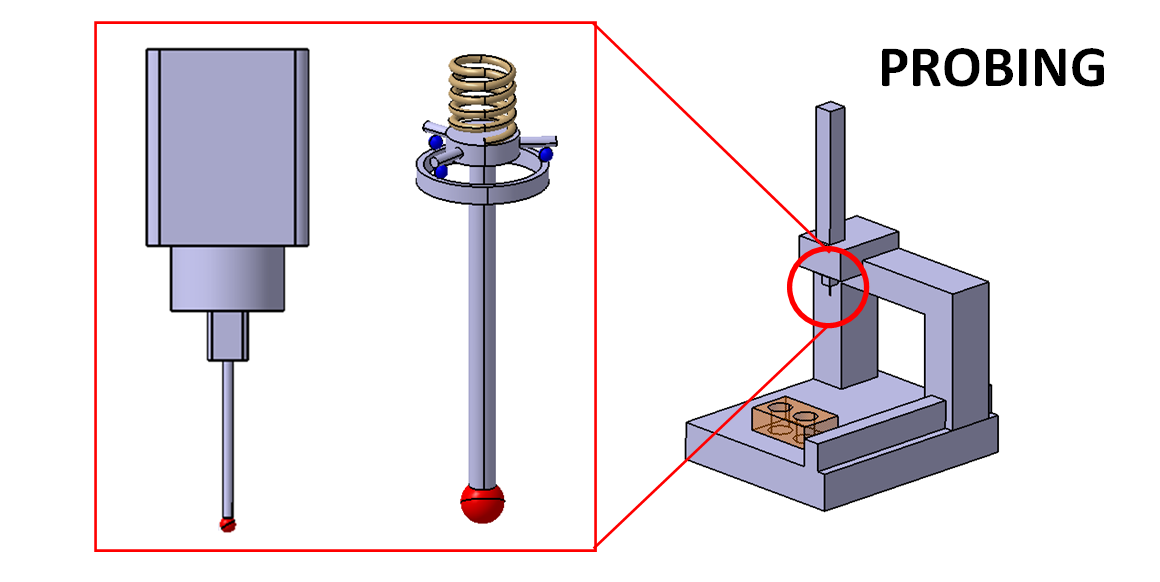
Probing system in a tactile coordinate measuring machine (tactile-CMM) is a fundamental component that acts as sensor to detect whether a stylus tip has touched the surface of a measured part and to record the position of the stylus tip (the coordinate of points on the surface) into the memory of the control system of the CMM.
Probing system is an integral part of tactile CMM and any other non-contact CMM (of course with different mechanisms). Because this probing system is the one that connect a tactile CMM to a measured part and provide the means to sense a surface.
In this post, we will discuss two main types of probing system for tactile CMM: active probing system and passive probing system. Each of this probing type has its own functionality for a specific measurement at hand.
Real commercial probing systems will be presented to give clarity about passive and active probing system for tactile-CMM.
(Note: All 3D illustrations were created by using a CATIA 3D modelling software)
Let us discuss the probing system of tactile CMM!
READ MORE: Tactile CMM: The reference of dimensional and geometrical measuring machine in industry.

The history of probing system of tactile CMM
In the beginning, the probing system of a tactile CMM only consists of a stylus that is only constructed by mechanical components without any electrical components.
The stylus at the early phase of probing system was used to manually positioned or moved by the operator of a tactile CMM to touch the surface of a measured part.
When the stylus tip has touched the surface of the measured part, the operator then manually presses a button to record the spatial coordinate of the points (based on the three-axis scale reading) into the controller memory of the CMM.
These manual processes of moving the stylus to a surface and pressing a button to record the surface point coordinate are a slow, subjective and not accurate operation.
The first revolution of probing system was started in 1972. In this year, Sir David McMurtry invented a probing system based on kinematic resistance. This probing system is then called touch-triggered probe.
The main motivation of Sir David McMurtry to make the touch-triggered probing system was that when he wanted to measure the geometry of small-sized fuel pipes. He found that it is very difficult to measure these pipes with existing manual probing systems.
From this touch-triggered probe invented by McMurtry, modern probing systems are developed for current generation of CMMs and their probing system with automatic touch sensing.
From history of the same period, not long after the invention of revolutionary touch-triggered probing system of Sir McMurtry, ZEISS company produced their first tactile-CMM machine UMM500 in 1973. The probing system used by UMM500 is a probing system with the capability of producing active probing forces.
This active probing forces capability can provide adaptive touching forces on a measured surface based on the stiffness-level and/or force reaction of the surface. If the surface has low-stiffness, then a small touching force should be small, and otherwise.
The touch-triggered probe of Sir McMurtry and the active-force probing system of ZEISS UMM500 are the foundation for current modern probing systems.
The basic configuration and mechanism of tactile probing system: Probing head and stylus system
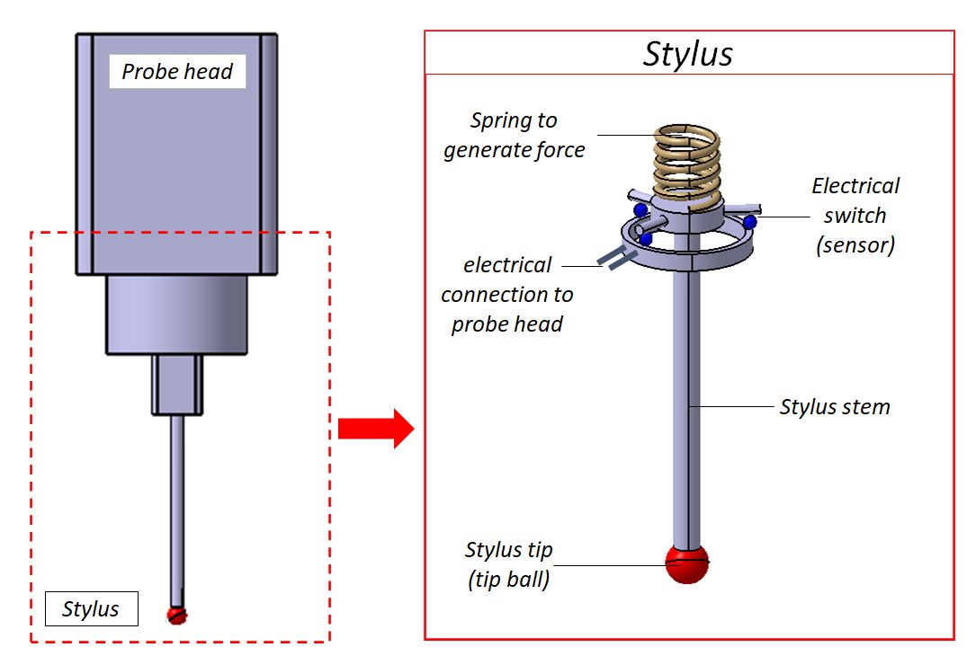
Probing system is divided into two main parts: probing head (sensor) and stylus system. Stylus stem is consisted of stylus stem (shaft) and stylus tip (tip ball).
Figure 1 below shows the basic configuration of probing system. Different probing system manufacturers will have the same basic configuration shown in figure 1. The probing system shown is a touch-triggered and force generating probe.
The detailed explanations of the basic configuration of the probing system shown in Figure 1 above are:
1. Stylus tip (tip ball)
The function of stylus tip is to touch (interact) with the surface of a measured part. A stylus tip is commonly made of ruby (a type of ceramic material) and has common characteristics as follow: it has high stiffness property, high wear resistance, has very low geometrical deviation, has high stability in different temperature and pressure variations.
2. Stylus stem (stylus shaft)
Stylus stem has a function to transfer physical contact information between the stylus tip and the surface of a measured workpiece (such as touching force or deflection of the stylus stem/shaft) to the detection sensor inside a probing head.
The main characteristics of stylus stem/shaft are it has a low thermal expansion, high stiffness, high strength and low mass. Common materials used to make a stylus stem are hardened steel, ceramic, fibre carbon and tungsten carbide.
3. Probing head or sensor
The function of this component is to evaluate physical contact information from the stylus system (tip and stem). Several sensor methods are based on electrical switch, touching force or displacement sensor. Current modern sensors nowadays in general can read the displacement and approaching/retraction direction of the stylus system.
4. Interface to CMM system
This interface has a function to transfer information of the detection point location/coordinate, from a sensor, that detect a touching between a stylus system and a measured surface, to the control system of a tactile-CMM. This information is then further processed and transformed the detected coordinate to the machine coordinate system (MCS) of the CMM.
5. Force generator
The function of force generator is to provide a pre-load force on a stylus system and (for active probing system) to provide adaptive touching force on the stylus tip on a measured surface and control the touching force such that the force is constant at the measured surface.
In general, the force is generated from an actuator mechanism based on voice-coil mechanism. This component is only found in an active probing system. For the implementation, this force generator can be in the form of a spring or flexure component/material.

General working mechanism of the probing system of tactile-CMM
The general mechanism of a probing system (sensor) is as follow (following figure 1). There is a kinematic system that consists of three small balls siting on a metal plate (see figure 1 above). When a stylus does not touch a measured surface, then those three balls altogether touch the metal plate. This three balls system acts as electrical switch.
If the stylus touches a measured surface, then at least one of the three balls will not touch the metal plate (figure 1 above). This condition will trigger an information or signal to the controller of the tactile-CMM to “tell” that the stylus tip has touched the surface.
From figure 1, a spring component on the interface between the stylus and probing head has a function to give a pre-load force to the stylus, so that the contact force between the stylus tip and the surface can be limited. In addition, this spring mechanism provided the ability of the stylus to perform a small over-travelling when touching the surface for deceleration of the CMM axes motion.
The spring can be in the form of a spiral spring or flexure plate. With a flexure system, there is an additional benefit compared to a spiral spring system. The additional benefit is that the flexure system can record or tell the touching or approaching direction of the stylus to the measured surface. This capability is obtained by attaching a strain gauge system on the flexure surface.
Active and passive probing system for tactile-CMM
For modern probing systems, there are two common probing types: active probing system and passive probing system.
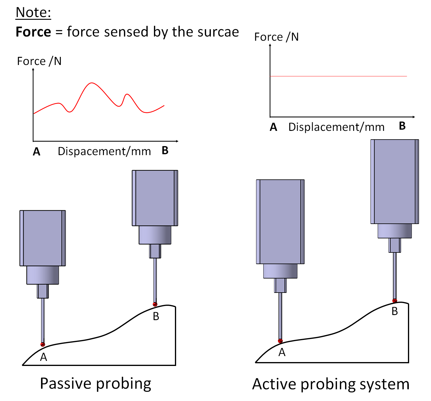
Figure 2 below shows an illustration of active and passive probing system. The detailed explanations of these active and passive probing systems are as follow:
1. Passive probing system
For passive probing system, the probing system cannot generate forces to its stylus system and can only detect touching/approaching direction on a measured surface. Passive probing system usually uses a flexure system by attaching a strain gauge sensor to sense the touching of a measured surface on X,Y and Z directions.
The strain gauge system measures the deflection of the flexure system. The resulted forces on the flexure are proportional to the deflection of the flexure. In figure 2 left, the touching force on a measured surface with a passive probing system is not constant. Instead, the touching forces vary with respect to the surface curvature of a measured part.
2. Active probing system
For active probing system, the probing head can generate forces on its stylus system when the stylus touches a measured surface. With this active system, the generated force can be controlled to adapt with the reaction force from the measured surface.
With this active system, the probing system can sense a surface that has not yet been touched before. In figure 2 right, with this active system, the force on the surface can be controlled to be constant regardless the curvature of the surface.
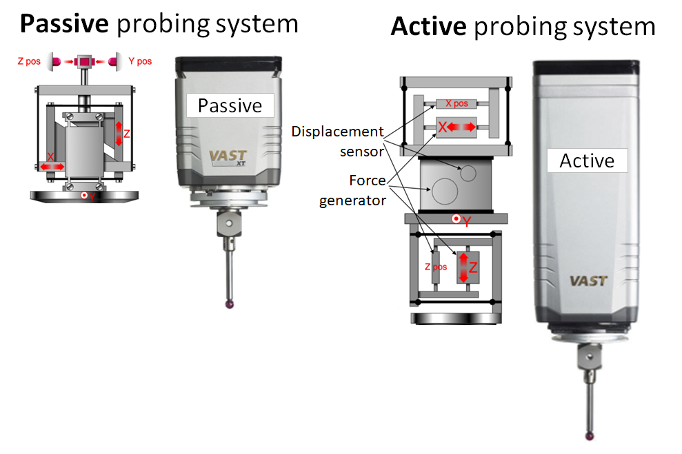
In figure 3 below, two commercial active and passive probing systems from ZEISS are shown. From figure 3, both of the probing systems are based on flexure mechanism.
As shown in figure 3, the active probing system has additional components to generate forces in three directions. Hence, physically, active probing system has a larger form compared to the passive probing system due to the additional components to generate forces.
One important thing to note is that the distance (the length of the stylus stem) between the contact sensor between a probing head and stylus tip ideally should be as short as possible. The aims is to minimise Abbe error due to the small deflection of the stylus stem when touching a surface.
However, there is a trade-off. If the stylus stem is too short, it will reduce the accessibility of the stylus to reach features on a surface to be measured!
READ MORE: Ten types of dimensional and geometrical measurement error.
Conclusion
In this post, the invention history, configuration and mechanism of the probing system of tactile-CMM has been presented.
The main components of a probing system are probing head (sensor) and stylus system. Probing head is the sensor to detect whether the stylus tip has touched the surface of a measured part or not.
In addition, two types of probing system: active and passive probing system have also been discussed.
Finally for clarity, commercial probing systems are also presented.
You may find some interesting items by shopping here.