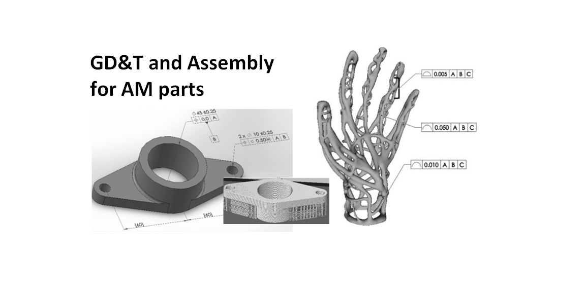
Geometric dimensioning and tolerancing (GD&T) and assembly of additive manufacturing parts
In this post, the challenge of applying geometrical dimensioning and tolerancing (GD&T) on additive manufactured (AM) or 3D printed parts will be discussed.
In this post, the challenge of applying geometrical dimensioning and tolerancing (GD&T) on additive manufactured (AM) or 3D printed parts will be discussed.
Unlike conventionally manufactured parts that have a defined and deterministic surface shape (thanks to the accuracy of conventional production machines, such as milling and injection moulding machines), additively manufactured parts have stochastic surface shapes (compared relative to conventionally manufactured part due to the nature of AM processes.
This stochastic surface shape imposes a challenge on how to apply GD&T on AM parts as well as how to verify the tolerance on the parts.
In addition, AM parts can have very complex geometry with arbitrary shape of surfaces. These types of surfaces will be tricky to apply GD&T symbols.
READ MORE: The economic benefits of tolerance stack-up analysis

The challenge of GD&T for tolerancing additive manufacturing parts
The main challenge of GD&T on AM parts is to assign correct tolerance values and symbols that have no ambiguity despite the surface quality of AM parts.
Commonly, the surface of AM parts has high roughness or waviness value. These surface characteristics cause the GD&T application becomes not so obvious for AM parts.
In addition, GD&T is a design language of a part designer to convey their design intend to manufacturing and quality inspection engineers. However, originally, the design intent is based on conventional manufacturing, such as milling, drilling and injection moulding processes.
Since, AM or 3D printing processes are relatively new compared to conventional manufacturing processes, there are some aspects that may be tricky to convey the AM process design intent to a manufacturing engineer.
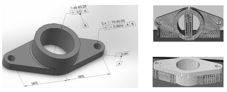
For example, for AM process, the part orientation is one of the critical parameters on an AM process. Hence, it is tricky to convey this part orientation for AM process engineer.
The part orientation in AM process will directly affectthe configuration of support structure, surface roughness [4] and the strength of the AM parts.
Figure 1 below shows an example of different part orientation on the same design will cause different surface roughness and support structure of the AM part. This information should be accommodated in GD&T symbols.
Another challenge of GD&T implementation for AM or 3D printed parts is how to specify tolerance of AM parts with an arbitrary and very complex shape.
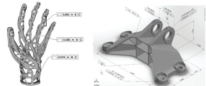
Figure 2 left below presents an example of an AM part with a very complex shape. Compared to a conventionally manufactured part (shown in figure 2 right), for this type of part, the shape is deterministic, and it is obvious which surface we can apply GD&T to.
On another hand, the AM parts with complex shape, shown in figure 2 left, does not have a flat surface where we can apply GD&T to. Another example of AM parts with complex shape is lattice structures or parts with internal complex structures.
GD&T should be able to accommodate these types of part complex shape as well as complex internal feature with complex geometry.
Another challenge related to GD&T of AM parts with complex shape is how to verify the tolerance of the AM parts at a quality inspection process.
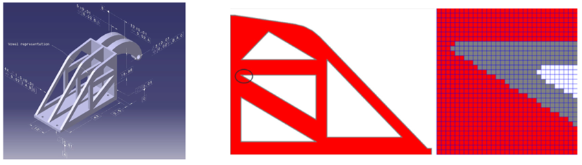
A proposal to verify GD&T on AM parts has been proposed by [3]. In their proposal, parts with complex shape are represented by voxel, that is a pixel in 3D form (see figure 3 right below).
Voxel is a small element with a defined geometry that can be used to represent a very complex shape by an approximation method. The variation of parts can be quantified by counting the number and size of the voxel.
READ MORE: Understanding fundamental assembly features: Mate and contact features
Conclusion
In this post, the challenge of applying GD&T specifications on AM parts has been discussed. In addition, the challenge of verifying GD&T specification of AM parts is also discussed.
Am parts have special characteristics compared to conventionally manufactured parts. For example, AM parts can have arbitrary and complex shapes, internal structure, no flat surface feature and high roughness surfaces.
In addition, GD&T should be able to represent or convey the AM process intended by a designer to a manufacturing engineer, for example, how to convey the part orientation of a part design for an AM process.
READ MORE: Geometric dimensioning and tolerancing (GD&T)
References
[1] Ameta, G., Lipman, R., Moylan, S. and Witherell, P., 2015. Investigating the role of geometric dimensioning and tolerancing in additive manufacturing. Journal of Mechanical Design, 137(11).
[2] Witherell, P., Herron, J. and Ameta, G., 2016. Towards annotations and product definitions for additive manufacturing. Procedia Cirp, 43, pp.339-344.
[3] Moroni, G., Petro, S. and Polini, W., 2017. Geometrical product specification and verification in additive manufacturing. CIRP Annals, 66(1), pp.157-160.
[4] Moroni, G., Syam, W.P. and Petrò, S., 2015. Functionality-based part orientation for additive manufacturing. Procedia Cirp, 36, pp.217-222.
You may find some interesting items by shopping here.