Geometric dimensioning and tolerancing: Wall-thickness analysis and LMC modifiers
In this post, we will discuss how to control wall thickness on our part design
In this post, we will discuss how to control wall thickness on our part design.
The “wall-thickness” on features are important to preserve structural integrity as well as to allow there is enough materials for subsequent machining processes (such as boring operation).
Mostly, when we design parts and assign geometric tolerances, we focus on controlling tolerances for part mating purposes.
That is, very often we focus on position tolerance with maximum material condition (MMC) modifier to make sure a shaft will fit its counter hole when manufactured in their tolerances [1].
However, when we position a hole or shaft on a part, we must consider the wall-thickness, such as the distance of the hole side to the nearest wall, the distance between two holes as well as distance between a slot to the nearest part side or the distance between two slots.
Because, if the wall-thickness is too small, we will lose the structure integrity of holes and shafts or we don’t have material volume to cut for subsequent processes.
The “wall-thickness” between external and internal features, including hole, shaft and slot is critical to the function of our parts.
Hence, the minimum “wall-thickness” between internal and external features should be controlled, calculated and should be above a minimum allowable magnitude. Typically, we considered “worst case” condition to calculate the “wall-thickness” of features [2].
By “worst-case” situation typically this condition is to protect the ability of parts to mate their counter assembly parts [3]. In this case, when MMC modifiers are used and the worst-case virtual condition is called [2][4].
With the MMC modifiers, we want to make sure the “worst-case” mating boundaries between two-mating parts are compatible and, statistically, we are sure that the parts always mate to each other when the parts are produced within their tolerances.
For “wall-thickness”, this property control is tightly related to least-material condition (LMC) modifier.
In the next sections we will discuss LMC modifier and how to calculate the wall-thickness of internal and external features based on their given geometrical tolerances.
READ MORE: Inspection of geometric tolerances: GO and NOGO gaging system
Description of the “wall-thickness” for external and internal features
When designing parts, we must think what happen when our external and internal feature of size are made at their worst-case.
In this worst case, not only the mating between parts, but also we must identify what will be the edge distance between internal and external features, for example, the edge distance between two adjacent holes, the distance between the edge of edge of a hole and part and the distance between two edges as well as the thickness between the inside and outside diameter of a tube.
When we know the wall-thickness at possible worst-case condition of our part features, we then analyse whether the given thickness satisfies our design requirements, such as the structural integrity is preserved and other characteristics depending on the final purpose of the parts [4].
From this activity, we can determine and calculate the minimum thickness required in our designs, typically in a worst-case situation.
By considering the minimum thickness at the worst-case situation, we are sure that any situation better than the worst case, our designed parts will satisfy their intended functionality.
For example, even if we design a hole that only function to reduce overall part weight and no mating function, when the hole is made at largest diameter, we must make sure the thickness between the edge of the hole and the part side is still thick enough to not compromise the part strength!
Note that, in case we want to only maintain the minimum wall-thickness (as the example just mentioned above) of an external or internal feature of size without the need to maintain its mating property, hence least-material condition (LMC) modifier should be used!
LMC modifiers are particularly used to make sure we still have structural integrity and/or have materials to cut in machining operations, such as finishing operation of a hole such as boring.
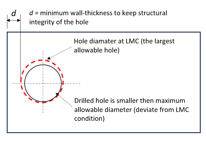
Figure 1 below shows the illustration of the use of LMC modifier to control the position of a hole. In this figure, the red circle is the largest allowable hole diameter at LMC condition (for internal feature).
When a hole is drilled smaller than its maximum allowable diameter (deviate from its LMC condition), there is a bonus for the hole to be able to have positon deviation but still keeping its minimum wall thickness requreiments (Figure 1).
Also, when the hole is made smaller from its possible largest diameter, there is excess materials to be cut for further finishing operation of the hole, such as boring operation, to smooth the hole internal surface.
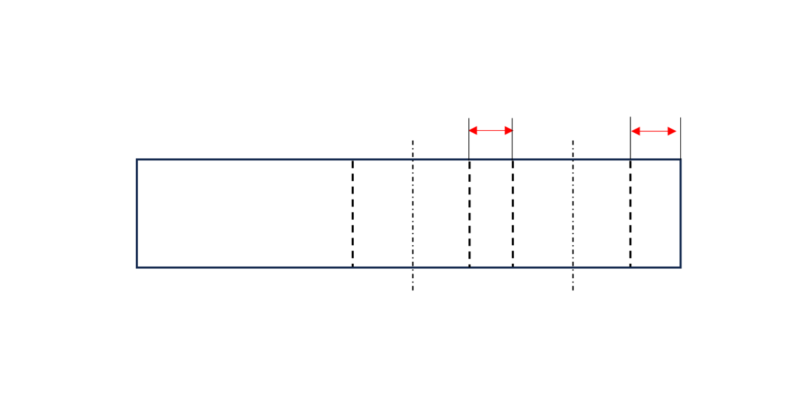
However, there is a special case. MMC modifiers should be used in only maintaining the distance (and there is no fit requirement) between two adjacent external features, for example keyboard button. By this MMC, when the external features are made smaller, there will be some bonus tolerance of their position while still maintaining the wall-thickness between the two external features [4].
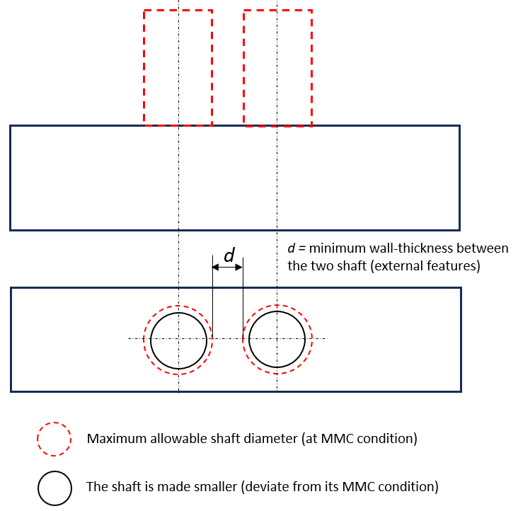
Figure 2 below shows an example of a special case where the minimum wall-thickness between two external features are control by MMC modifier. In this figure, the feature in red-dash line is the maximum allowable diameter (MMC condition) and the black line is the manufactured feature with diameter less than the MMC condition (the allowable maximum diamater for external feature).
When the shaft made smaller, hence there is a bonus where the shaft can shift around while keeping the minimum distance between the two shafts to be still satisfied.
Calculation of the “wall-thickness” for external and internal features
Typically, LMC modifier is used to control “wall-thickness” property of an external or internal feature of size.
Related to LMC modifier, there are two boundary condition we need to know:
- For internal features (such as hole).
Outer boundary (of internal feature) = LMC (maximum allowable diameter) + Applied geometric tolerance at LMC (such as position).
- For external features (such as shaft or keyboard button).
Inner boundary (of external features) = LMC (minimum allowable diameter) - Applied geometric tolerance at LMC (such as position).
Typically, “wall-thickness” is calculated by subtracting one boundary from another boundary and dividing it by two.
Example 1: The wall-thickness between a simple external and internal features
Suppose we have a part with external feature (a shaft) and internal feature (a thorough hole on the shaft) as shown in figure 3 below.
In this figure, the wall thickness is the difference between the outer and inner diameter of the shaft. When designing this wall thickness, we should have determine what is the allowable thickness (maybe using a finite element simulation) of this shaft to keep its structural integrity intact when delivering its functionality.
Hence, our geometric tolerances should control such that in the worst case when this shaft still within its tolerance limit, we can still have the wall-thickness above or equal to the allowable minimum thickness.
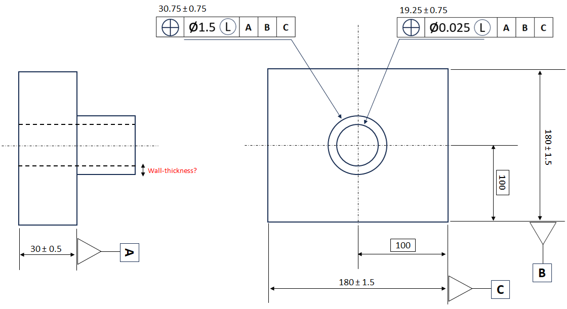
Based on figure 3 above, the wall thickness of the shaft with the hole is calculated as follows:
- Shaft:
Inner boundary of the shaft = 30 (LMC for the shaft as minimum diameter for external feature) -1.5 (Position tolerance at LMC)
Inner boundary of the shaft =28.5
- Hole:
Outer boundary of the hole = 20 (LMC for the hole as maximum diameter for internal feature) +0.025 (Position tolerance at LMC)
Outer boundary of the hole =20.025
- The wall-thickness:
The thickness = (Inner boundary of shaft – outer boundary of hole)/2
The thickness = (28.5-20.025)/2=4.237
Hence, the minimum thickness of the shaft when it is manufactured at its worst allocable limit will be 4.237.
Example 2: The wall-thickness between a pattern of holes and the outside diameter of a cylinder
This example presents a wall-thickness calculation between a pattern of four holes on a cylinder and the outer diameter of the cylinder.
Figure 4 below shows the 2D drawing of the cylinder with its 4-hole pattern.
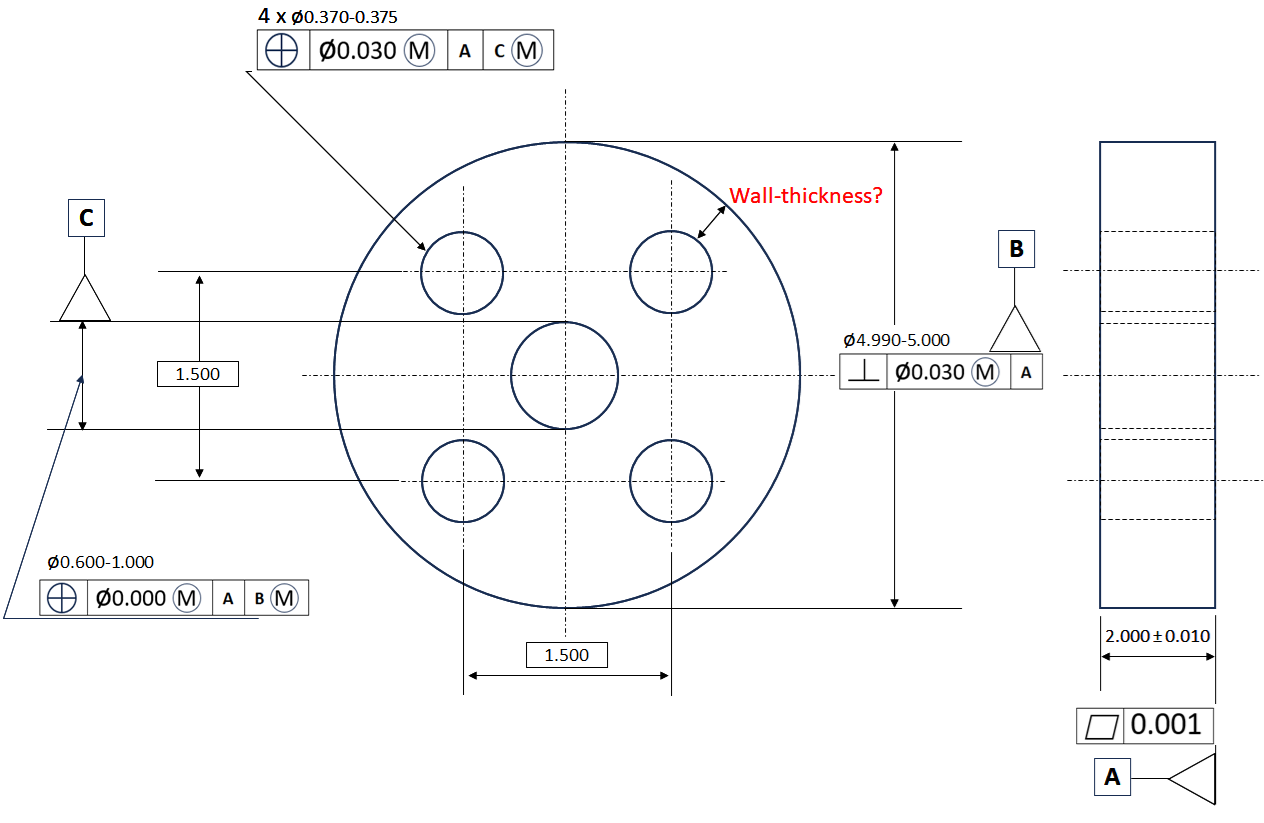
From figure 4, the wall-thickness is defined as the difference between the inner boundary of the main cylinder (external feature) and the outer boundary of the holes (internal feature).
In this case, we will see that displacement of the hole features also affect the wall-thickness of the 4-hole and the outer boundary of the cylinder.
In this example, since the hole patters also refers to datum C of the central hole. Hence, when the central hole (Datum C) displaces or shift, this displacement will also affect the wall-thickness of the hole pattern.
The wall-thickness calculation for this case is as follows.
- The main cylinder’s outer diameter
Inner boundary of the outer diameter of the cylinder = 4.990 (the LMC of the outside diameter) -0.040 (Perpendicularity tolerance of the outside diameter)
Inner boundary of the outer diameter of the cylinder = 4.950
- The 4-hole patter outer boundary
Outer boundary of the hole pattern = 0.375 (the LMC of the hole in the patters) + 0.035 (position tolerance of the hole patters)
Outer boundary of the hole patter = 0.410
- Diameter of circle across the 4-hole pattern centre point
Diameter of the bolt hole circle (the 4-hole pattern) = 1.6 (bolt hole square) x 1.414 (square root of 2)
Diameter of the bolt hole circle (the 4-hole pattern) = 2.263
- Resultant condition
Resultant condition of the outer diameter of the cylinder without Diameter of the bolt hole circle (the 4-hole pattern) = 4.950 (Inner boundary of the outer diameter of the cylinder) – 2.263 (Diameter of the bolt hole circle (the 4-hole pattern))
Resultant condition of the outer diameter of the cylinder without Diameter of the bolt hole circle (the 4-hole pattern) = 2.687
- Outer boundary of the resultant condition
Outer boundary of Resultant condition of the outer diameter of the cylinder without Diameter of the bolt hole circle (the 4-hole pattern) = 2.687 (Resultant condition of the outer diameter of the cylinder without Diameter of the bolt hole circle (the 4-hole pattern))-0.410 (Outer boundary of the hole patter)
Outer boundary of Resultant condition of the outer diameter of the cylinder without Diameter of the bolt hole circle (the 4-hole pattern) = 2.277
- Displacement effect of the central hole
Total material as its produced = 2.277 – 0.400 (movement of datum C allowed with respect to the outer diameter as the difference between max and min diameter) – 0.400 (displacement due to datum feature shift bonus at MMC)
Total material as its produced =1.477
- Hence, the wall-thickness of the 4-hole pattern = Total material as its produced/2
Hence, the wall-thickness of the 4-hole pattern = 1.477/2 = 0.7385
Factor to consider are in this case study are as follows:
- Datum C (the central hole) may be out of position of 1.000-0.600=0.400 when it is produced at its LMC (maximum diameter).
- When datum C is made bigger deviating from its MMC condition (smallest diameter), there will be allowable displacement of the 4-hole location with respect to the datum axis C. This is due to the MMC modifier to datum C in the 4-hole pattern positional tolerance.
Conclusion
In this post, we have discussed how we calculate the wall thickness between external and internal features such that we still can preserve the structural integrity of the whole part containing the features or we can still have enough materials for subsequent manufacturing processes.
The “wall-thickness” of features are for example the distance between the hole and edge of a part, the thickness of a tube and the minimum distance between two holes.
To control the wall-thickness of features, we typically use LMC modifier to control the thickness. However, there is some special case where we use MMC instead of LMC to control wall-thickness.
For example, the special case of using MMC to control wall thickness is the distances between two external features, such as the distance of two adjacent buttons.
Two case studies have been presented to demonstrate the use of LMC to control the wall-thickness between external and internal features.
Reference
[1] ASME Y14.5-2009, Dimensioning and Tolerancing: Engineering Drawing and Related Documentation Practices.
[2] Meadows, J.D., 2017. Geometric Dimensioning and Tolerancing: Applications and Techniques for Use in Design: Manufacturing, and Inspection. Routledge.
[3] Whitney, D.E., 2004. Mechanical assemblies: their design, manufacture, and role in product development. New York: Oxford university press.
[4] Fischer, B.R., 2004. Mechanical tolerance stack up and analysis. CRC Press.
You may find some interesting items by shopping here.