Geometric dimensioning and tolerancing: Datum selection
This post discusses the basic principles of datum in geometric dimensioning and tolerancing (GD&T)

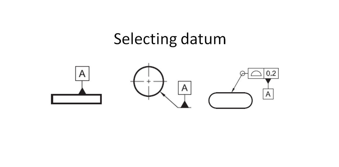
This post discusses the basic principles of datum in geometric dimensioning and tolerancing (GD&T) [1], including selecting optimal datum features on a part, ruling of datum features, applying geometric tolerances on datum features, applying the most suitable material condition for datum features, assigning datum features for part stabilisation, fixturing parts on their datum features, and eliminating spatial freedom of parts from datum features.
Datum is an imaginary point or axis or plane used to create a coordinate system as reference for any measurement on parts. The created coordinate system is called as “datum reference frame (DRF)”.
DRF is mathematically represented when we perform inspections using a coordinate measuring machine (CMM) or when we setup a workpiece (part) coordinate system (WCS) on a computer numerical controlled (CNC) system.
Datum is constructed from a datum feature. Datum feature is a physical (real) surface on a part representing a datum. In practice (manufacturing, inspection or assembly processes), a datum feature is represented by a datum feature simulator (or in short datum simulator), which is a physical (real) surface which is not on the part.
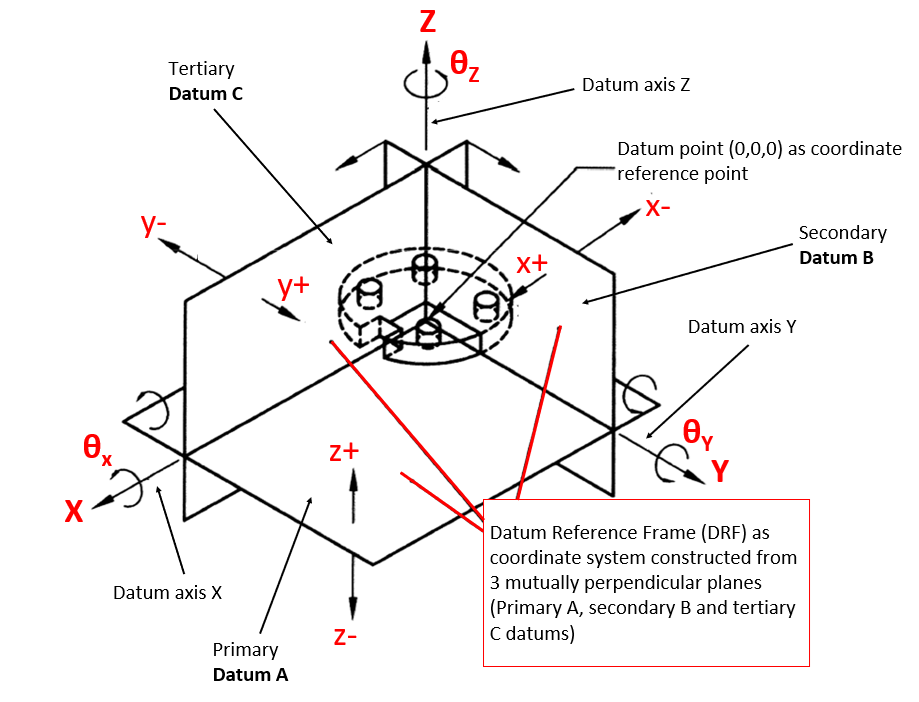
A complete DRF or part coordinate system has three mutually perpendicular planes. DRF is needed to eliminate the six degrees of spatial freedom (three rotational and three linear) of part movement as well as location and orientation reference of other features on the same parts [2].
Since Datum features need to be represented in practice, we need to simulate datum features by using manufacturing and inspection equipment, for example, fixturing. The datum simulation in represented as datum feature simulator.
And yes, these datum feature simulators are not perfect!
A physical surface, used as Datum simulator, will have physical contact with Datum feature (representing a datum which is an imaginary feature defined in our 2D drawing). This datum simulator will construct a reference for the orientation and location of other features on the same part during an assembly, manufacturing (machining) setup and inspection setup.
In some cases, physical manufactured surfaces (acting as datum simulator) have very rough surfaces or warpages due to manufacturing constraints such as cost or process limitations (such as welding). If the entire surface is used as datum in their design, this roughness may create variation on the DRF and will be amplified by means of tolerance propagation to other features.
Hence, in this situation, datum target points, lines or areas are used to construct DRF instead of an entire surface.
READ MORE: Geometric dimensioning and tolerancing (GD&T): Rule #1 and Rule #2
If you want to support me developing this blog, you can support me here.
Fundamental requirements of datum features
There are essential characteristics that datum features should have as follows:
- Datum feature should have a specific functionality on a part, that is it serves a specific purpose on how part operates. For example, a datum feature is a contact surface with respect to its mating part, is a shaft to fit the cylinder of its mating part or is a hole where a mating shaft or assembly pin will sit.
- Datum feature should be representative of mating features, seating features and/or alignment features. The reason of this characteristic is that to make sure if a part is passing an inspection process when the part features are oriented or located with respect to the DRF constructed from the datum feature, the part will perform its function as desired or designed.
- Datum feature should be accessible during manufacturing, assembly and inspection processes.
- Datum feature should be repeatable from manufacturing process to manufacturing process and from inspection setup to inspection setup. The reason is that this repeatable characteristic is instrumental to have repeatable measurement data (repeatability) or repeatable manufactured parts. To event make datum feature repeatable, typically datum feature will have more strict geometrical tolerances (such as form and orientation) compared to non-datum features. Primary datum has always the strictest tolerances.
To summarise, datum feature should be functional, representative, accessible and repeatable.
Rule-of-thumbs to select datum features and other GD&T symbols
This practical rule-of-thumbs [2] can be used as a guide in determining datum features, material conditions and other GD&T symbols as follows:
- Primary datum feature should be a sufficiently large planar (base) surface which seat on its mating part surface and has a good 3-high-point contact. We control this primary datum surface with flatness tolerances (if the surface is sufficiently large).
- Another good primary datum features are cylindrical features that fit inside one another like functional shafts or pin or holes. These features should have a cylindricity tolerance control to improve the repeatability of this feature and to provide a datum axis from which to locate and orient other features.
If a functional cylindrical features are selected as secondary datum or diameter is used as a secondary datum feature, consider either to apply either perpendicularity referring to the planar primary datum (if other features are to be measure with respect to this cylinder axis) or positional tolerances (if this feature needs to be measured from other datum to determine the cylinder location).
- Note that, it is not all functional features can be used as datum features. It will be easier to have a small number of datum features which enough to setup a proper DRF. Minimal datum features will allow us to have fewer set-ups and saves time for manufacturing and inspection as well as avoiding over-constraints.
- When there are equal alternatives for datum features, always choose features with the most surface area and/or have the most accessible on which to set-up.
- Not only creating a reference coordinate system, a DRF is also important to stabilise parts to create a physical description on how to locate and orient the part in assemblies.
- It is expected to have some degree of errors of alignment between original and subsequent DRF due to tolerance accumulation induced by switching from one DRF to another (in mating parts).
- When a part has more than one mating components, we will need to switch datum in the middle of a process (manufacturing or inspection or assembly) to accommodate different mating parts on the same part.
- If there is one mating part mates with another single mating part, regardless number of mating features, only one set of DRF will be used.
- Avoid making a conflict on different datum features as there are only 6-degree of freedom to constraint. This conflict will create over-constraint. That is, each datum features should have different constraining function (for different translations and rotations)
- If the goal is to make sure parts always mate together when manufactured in tolerance (for example, regardless if pins fit in the very centre of holes but anywhere in the holes or datum features do not need to be centred between mating parts), then the maximum material condition (MMC) symbol after geometric tolerances should be used (circled M). MMC symbol should not be used for features that do not mate. MMC implies a bonus tolerance if a feature deviates from its MMC condition (such as a hole made larger or a pin made smaller).
- The use of least material condition (LMC) indicates that the preservation of materials and/or wall-thickness control is the most important requirement instead of mating functionality. For example, in casting drawing, since there will be subsequent machining process to be applied to reach a required dimensional and surface finish accuracy, we need to put LMC symbol to preserve materials such that there is material left to machine. LMC implies a bonus tolerance if a feature deviates from its LMC condition (such as a hole made smaller or a pin made bigger).
- The use of regardless of feature size or regardless of material boundary concepts (RFS) indicate that any geometric deviations are not desired. It implies there is no bonus tolerance. Usually, this RFS is applied to a cylindrical datum feature where this feature is used to refer a location of spinning parts (balance requirements). Another example of the use of RFS is for uniform fit requirements in the context to provide sealing functionality.
- Corresponding features of mating parts should also be as datum features on its part (whenever possible). By doing this, we will ensure proper part interface and assembly.
- When a selected datum feature cannot be accurately manufactured (such as rough surface, rough casting or flexible/compliant surface) and cannot be practically control by applying tolerances, in this situation, we may consider Datum target.
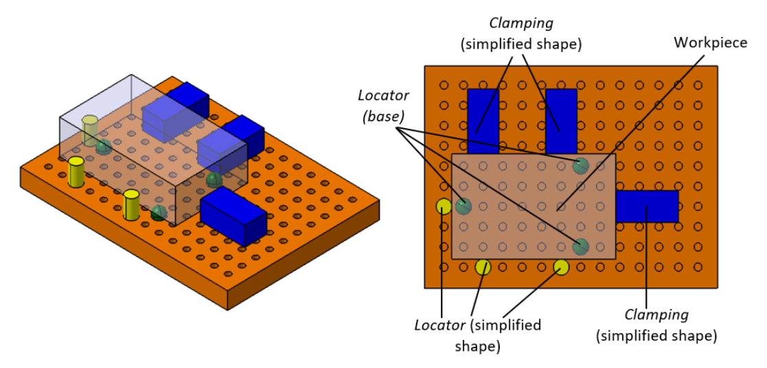
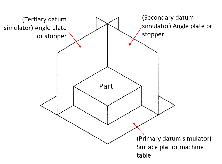
- If we do not use datum target, hence we should do the following. To establish datum plane or axes, we should use datum surface extremities or high points. In practice for planar datum surface, this means that we use at least 3 high points on the surface into contact with the primary datum plane simulator, at least 2 high points on the surface into contact with the secondary datum plane simulator, and at least 1 high points on the surface into contact with the tertiary datum plane simulator. Figure 1 below shows the illustration of this practical approach. Typically, the datum feature simulators are stoppers or locators.
READ MORE: 3D tolerance stack-up analysis with examples
Degree of freedom
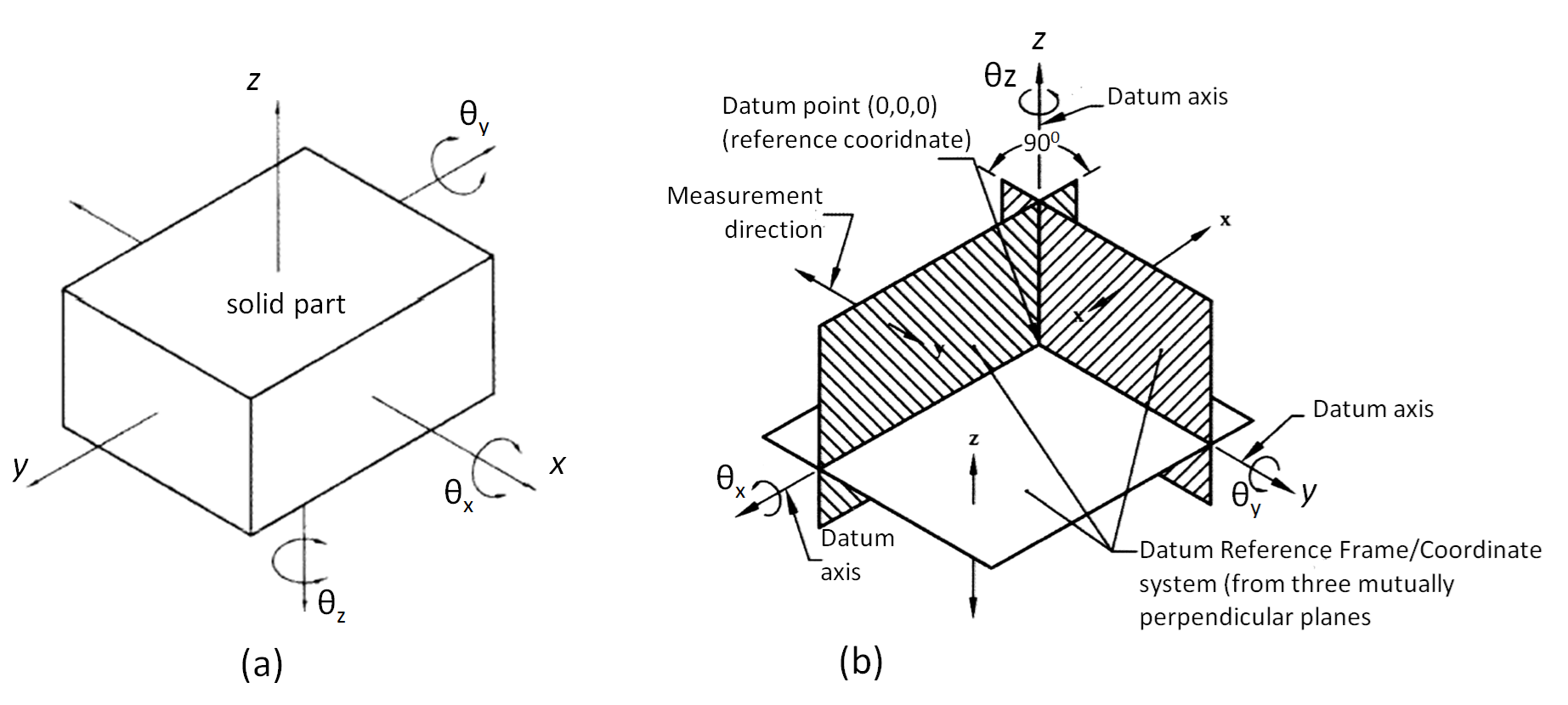
Any part at 3D space will have a 6-degree of freedom (DoF) motion, which are: three translational motions in x-, y- and z- directions and three rotational motions around x-, y- and z-axis.
Figure 2 below shows the 6-DoF motion of a part in space and the DRF of the part constructed from three mutually perpendicular datum planes.
In figure 2a, a 3D object can move in any directions when there are no constraints on its motion. In reality, in part machining, part assembly and part inspection, this 6-DoF motion should be constrained by using DRF as shown in figure 2b.
DRF is not only for constraining part but also for creating a reference coordinate system where other tolerances on the part refer to. From figure 2b, the DRF consists of primary datum (the bottom plane), and secondary and tertiary datums (the two side planes).
From these three datum planes, the reference coordinate system is established, and the part is kinematically (exact) constraint over 6-DoF motion.
To realise the DRF from defined primary, secondary and tertiary datum plane or datum features (as shown in figure 2), datum features simulators are used.
Figure 3 below shows how datum simulators are the physical surfaces representing datum features or planes in real part manufacturing, inspection or assembly processes.
In figure 3, the primary datum feature (the base of the part) is represented (simulated) in real situation as the surface of a plate or machine table where the part is placed and rests on its high point of contact (minimum 3 high points).
The primary datum simulator constraints the part in 3- out of 6-DoF, that are two rotational motions (along x- and y-axis) and one translational motion along z-axis.
The secondary and tertiary datum are represented (simulated) in real situation as the surface of angle plates or stoppers or locators (as shown in figure 1 above).
The secondary datum plane rests at least on its 2 high point on the datum simulator. Meanwhile, the tertiary datum plane rests at least on its 1 high point on the datu simulator.
The secondary datum simulator constraints 2 of the other 3 remaining DoF, that are one rotational motion around the z-axis and one translational motion along the X or Y axis.
And the last tertiary datum simulator constraints the last 1-DoF, that is translational motion along X- or Y- axis. At this point the part will be constraint in 6-DoF.
Of course, a block part is the simplest case, more complex parts will have more complex datums features and hence more complex datum feature simulators (fancy jig, locator and fixtures) compared to the simple block-shape part.
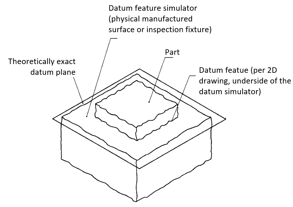
Note that datum simulator is a manufactured real physical surface which is not perfect due to manufacturing process errors and variations. also, the manufactured datum features have surface errors or variations.
Hence, these variations of manufactured datum surfaces and datum feature simulators contribute to the total tolerance stack-up on a part (typically represented by variations in flatness) [4].
Figure 4 below shows the illustration of an imperfect datum simulator as a physical surface representing a datum feature.
Examples of selecting datums
In this section, we will discuss a real practical example of datum features selection on a cylindrical part.
Figure 5 below shows the 2D drawing of a cylindrical part with its tolerance and datum features. In figure 5, there are three datums: Primary datum A, secondary datum B and tertiary datum C.
Datum A is the base of the cylinder where the part placed on a machine or inspection table. Datum feature A is the largest and stable surface on the part. Since this is the first datum, no-relation geometrical tolerance is assigned. Typically, flatness tolerance is assigned to planar surface) or cylindricity tolerance is assigned to cylindrical surface.
Datum B is the axis of the cylinder. The datum plane is built along the axis direction of the cylindrical part. For this datum, perpendicularity tolerance (related tolerance) with respect to datum A is assigned.
Finally, datum C is the symmetry axis of the slot feature. The datum plane is built along this symmetry axis of the slot feature. Positional tolerance with respect to datum B and A is assigned for this datum C.
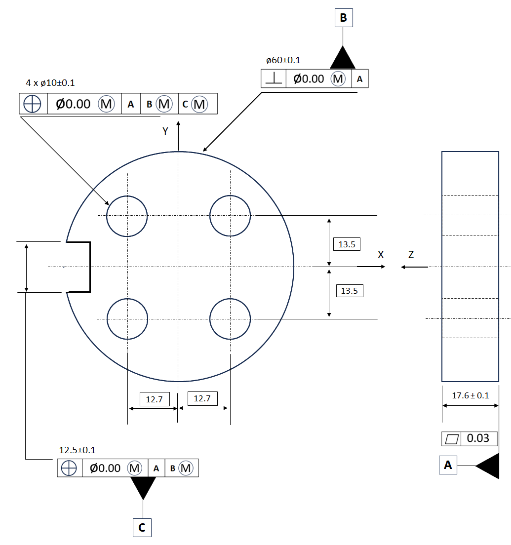
Figure 6 below shows the realisation of the DRF of the example part in figure 5 above. The datum plane A is a theoretically planar surface in contact with the base of the part.
The datum B plane is a theoretical plane along the cylinder axis and perpendicular to the datum A plane.
Finally, the datum plane C is a theoretical plane along the symmetry axis of the slot passing through the cylinder axis (location tolerance) and perpendicular to the datum A plane.
The DRF of the part is the intersection point of the three mutually datum A, B and C plane. The point (0,0,0) is at the centre of the cylinder coincident with the base (as shown in figure 6 below).
READ MORE: Manufacturing and space: How GD&T tolerancing is instrumental for rocket and satellite launcher
Conclusion
In this post, we have discussed the concept of datum, datum features and datum feature simulator (datum simulator). In addition, some guides to select features on parts as datum have also been discussed.
We also discussed the concept of degree of freedom and how datum features construct not only reference coordinate system but also provide a way to constraint the degree of motion freedom such of a part that the part is static for assembly, manufacturing and inspection processes.
Finally, examples of the application on selecting datum features on a practical part have also been discussed.
The key take ways are datum features should be functional surfaces (very often mating surface) and should provide kinematic constraint for 6-DoF motion.
Reference
[1] ASME Y14.5-2009, Dimensioning and Tolerancing: Engineering Drawing and Related Documentation Practices.
[2] Whitney, D.E., 2004. Mechanical assemblies: their design, manufacture, and role in product development. New York: Oxford university press.
[3] Meadows, J.D., 2017. Geometric Dimensioning and Tolerancing: Applications and Techniques for Use in Design: Manufacturing, and Inspection. Routledge.
[4] Fischer, B.R., 2004. Mechanical tolerance stack-up and analysis. CRC Press.
If you want to support me developing this blog, you can support me here.
You may find some interesting items by shopping here.