Tolerance stack-up analysis: The effect of manufacturing setup changes
In this post, we will discuss the effect of setup (datum) changes from design drawing to manufacturing process drawing on the total tolerance stack-up of part assemblies.
In this post, we will discuss the effect of setup (datum) changes from design drawing to manufacturing process drawing on the total tolerance stack-up of part assemblies.
We know that the process of an assembly process itself creates variations, such as from unrepeatable part positioning procedures, assembly forces to fit a part into another and environmental variations as well as other assembly variation sources.
However, those variations are only half of the story. Another relevant assembly variations comes from the changes in datum between the design drawing and manufacturing process drawing [1].
Different datums mean different manufacturing setup!
and hence, adding to the total assembly or machining errors.
Next sections discuss these aspects with a simple case study to clarify the effect.
READ MORE: 3D tolerance stack-up analysis with examples
Different datum between design and manufacturing
In the assembly or machining of a mechanical product, many sources contribute to geometrical variations of the final key characteristics (KC) of product.
Those variation sources can be from assembly procedures, operator as well as from assembly/machining sequences and processes.
In assembly or machining, the way we, as an assembly/machine operator, locate and orient parts may differ to the part datums specified in design drawings and their geometrical tolerances [2].
These differences are due to, for example, the need of part orientation adjustment for machine tool accessing features to machine, the use of multiple fixtures to machine different features, operator positioning mistakes, the effect of applied forces by the operator of an assembly process, the effect of fixturing forces on parts and other factors.
As we can see, fixtures in machining and assembly processes play a crucial role in contributing to the final part accuracies.
The best condition is always to use a single fixture for all machining or assembly operations such that the total accumulated error (error stack-up) will be only due to the fixture error itself and not due to datum variations.
However, in many cases, to have a complete machined parts or assembled products, we would have multiple part orientations achieved by using multiple fixtures.
These different orientations typically will cause we orient and locate parts differently with respect to the design datum reference in design drawings.
In this condition, we will have additional errors on top of the designated tolerance stack up.
We will discuss this matter with a simple case study to clarify the effect of different datum to the tolerance stack up of a part.
A case study
We use a simple case study of a cylindrical part which has additional stack up error due to assembly error causing improper part placement (not expected as per the designed datum).
Particularly in this example, we investigate the effect of operator’s applied forces that cause assembly variations such as the part orientation is not following its datum features.
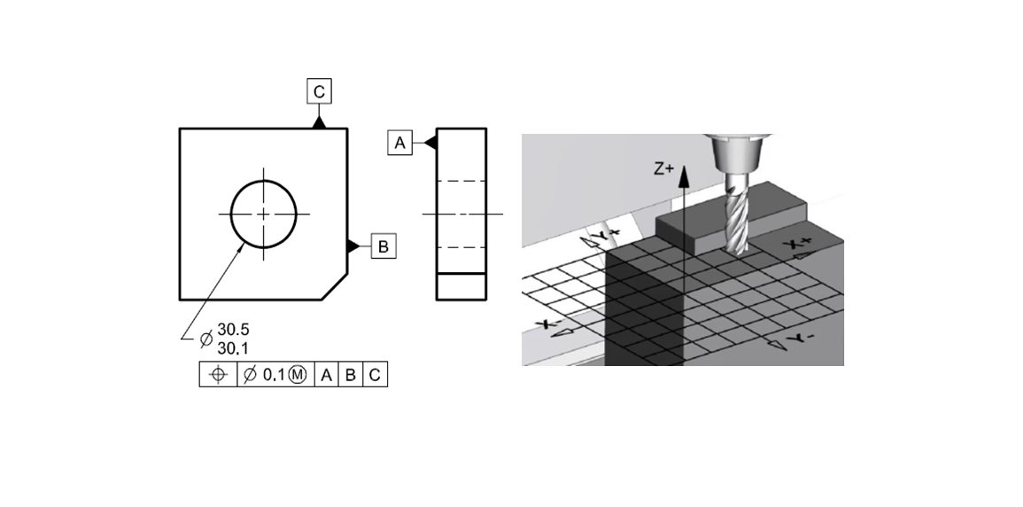
Figure 1 below shows the simple cylindrical part having two datums: Datum A and Datum B. all units are in mm. The part has two cylinders one with nominal diameter of 6mm and another one with 2mm.
Datum A is a flat surface to contact with a mating surface and has a flatness tolerance of 0.002mm.
Datum B is the axis of the big cylinder with 6mm with perpendicularity tolerance of 0.002mm with respect to the Datum A.
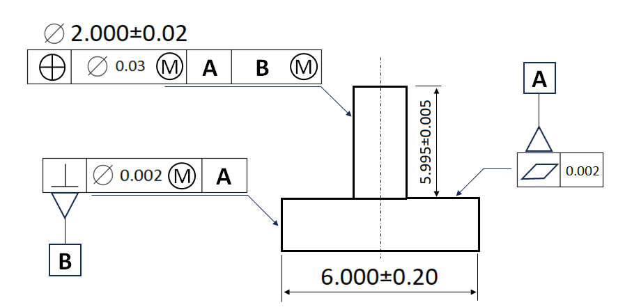
To guarantee that the mating hole of the cylindrical part always accommodates the small cylinder (shaft) of 2mm diameter provided within its tolerance, the mating hole diameter should be the virtual condition of the 2mm cylinder of the part.
The virtual condition of the 2mm cylinder is as follows:
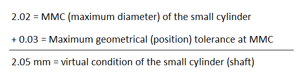
That is, to assure the 2mm shaft can always enter its mating hole, the mating hole diameter should be set to 2.05mm.
That is, the worst condition is that the mating hole for the small cylinder (shaft) is made at the virtual condition size of 2.05mm and the small cylinder (shaft) is made at its smallest allowable diameter.
In this worst condition, assembly errors are prone to happen!
Let’s now look at what happen when an operator accidently pushes the part to one side as shown in figure 2 below.
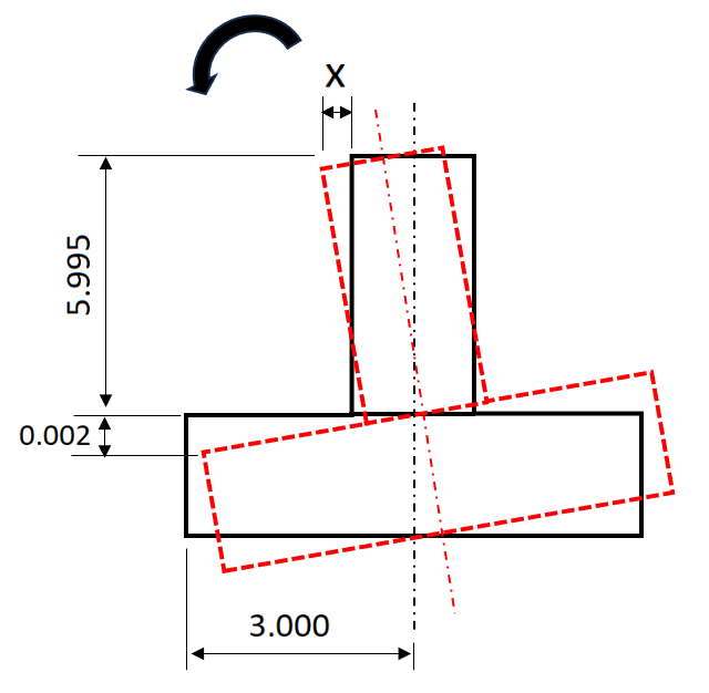
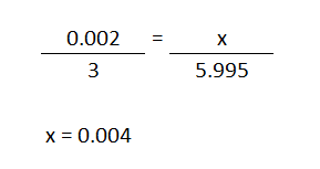
In this figure 2, due to assembly mistakes or errors, the 2mm cylinder (shaft) shifts about 0.004mm from its expected orientation. The shift is calculated as follows:
This 0.004mm shift eats up the position (geometric) tolerance of the 2mm cylindrical (shaft) feature from 0.03 to (0.03-0.004) = 0.026mm.
Another way of looking at this situation is that in order to compensate our original position tolerance, we need to add this assembly error effect into the position error for the 2mm cylindrical (shaft) feature of the part from 0.03mm to (0.03+0.004) = 0.034mm.
However, with this tolerance increase, we will have an increase on the tolerance stack up of the part and its assembly!
Hence, we need to be aware of this situation and must consider carefully on how we assign tolerances on features considering our main assembly KC requirements as well as the effects of possible assembly errors.
READ MORE: Understanding fundamental assembly features: Mate and contact features
Conclusion
In this post, we discuss additional error stack up due to machining and/or assembly process variations. In machining and assembly processes, very often we orient and locate parts several times due to the need to access the features of the part.
This several re-positioning causes we place the part not following the intended part positioning and orientation as per the part’s design drawing.
This difference in part positioning with its designed datum cause additional error stack up on the part features or the assembly KCs.
Any errors in assembly or machining due to fixture, machine or operator setup as well as fixture forces and assembly force on parts will eat up the geometrical tolerances assigned to features.
The best practice is to always minimise the use of fixtures and number of part setups in machining and assembly operations.
Reference
[1] Meadows, J.D., 2017. Geometric Dimensioning and Tolerancing: Applications and Techniques for Use in Design: Manufacturing, and Inspection. Routledge.
[2] ASME Y14.5-2009, Dimensioning and Tolerancing: Engineering Drawing and Related Documentation Practices.
You may find some interesting items by shopping here.