Geometric dimensioning and tolerancing (GD&T): Rule #1 and Rule #2
In this post, we will go to basic and discuss the two fundamental rules of GD&T: Rule #1 and Rule #2.
GD&T has been widely adopted as the complementary of traditional “+/-” tolerancing so that we can remove ambiguity in understanding the design intent of parts.
With GD&T, we as mechanical designer can convey our intent of how parts should function and be joined or assembled together, how the parts should be manufactured and how the parts should be inspected.
In this post, we will go to basic and discuss the two fundamental rules of GD&T: Rule #1 and Rule #2.
We will start with a very brief history of GD&T to understand the motivation and evolution of the two GD&T rules.
At the end of this post, we will understand how GD&T idea was originally conceived and the two basic premises of GD&T: the rule #1 and rule #2.
Let’s dive into it.
READ MORE: Understanding fundamental assembly features: Mate and contact features
A brief history of GD&T
The initial period of manufacturing was called “all in-house and fit-for-one manufacturing” where all parts constructing an assembled product are all made in-house and the parts are made to fit each other together to construct a particular assembled product.
The parts were not interchangeable!
That is, the same parts cannot use for other assemblies with the same design. Because each part is adjusted (finished) to fit together other parts at the same batch for the same particular assembled products.
Starting around the beginning of the 20th centuries (early 1900), manufacturing industries started to produced products in high-volume, particularly pulled by the need to supply war equipment.
In addition, various parts for assembled products started to come from different suppliers supporting a big assembling manufacturer for complete products.
Driven by the needs of part interchangeability for mass productions and globalisation, and the increase knowledge of manufacturing where all processes are not perfect (induced some errors on produced parts), initially for weapon productions and line manufacturing for automobile, the needs of allowing some deviations or produced parts started to emerge.
Near the beginning of World War II, Stanley Parker who is a worker at the Royal Torpedo Factory in Alexandria, West Dunbartonshire, Scotland, realised and observed at a shop floor that there were good parts satisfying functional requirements, but rejected due to out of tolerance when the parts were measured.
Motivated by these observations, Parker developed “tolerancing practices” in his shop-floor.
In general, two or more parts are joined or assembled together through their assembly features.
These assembly features are commonly in the form of holes (internal features) and pin (external features), including fastener and shaft.
Hence, Parker developed the concept of “True Position” which is the originator of GD&T.
From Parker’s work, he published the first work on GD&T in 1940 with title of “Notes on Design and Inspection of Mass Production Engineering Work”
After that, in 1956, Parker published “Drawings and Dimensions” technical guide.
In the US, initial GD&T related standard was published by the US military in the 1949 as “MIL-STD-8. In 1953 to include GD&T ‘Rule #1’”.
Then in 1957, the American Society of Mechanical Engineers (ASME) published the first version of GD&T standard: ASA Y14.5 which now become ASME Y14.5 standard for GD&T and is widely used around the world.
READ MORE: 2D tolerance stack-up analysis with examples
GD&T rules #1 and #2
The observation of Stanley Parker of the royal torpedo factory regarding some rejected parts actually still satisfies functional requirements, that is, the parts are still useable although the parts slightly out of tolerance.
This observation becomes the motivation of GD&T rule regarding some bonus tolerances (relaxed tolerance) when certain parts deviate from their nominal dimensions.
The two GD&T rules: Rule #1 and Rule #2 are as follows.
GD&T rule #1
GD&T rule #1: Envelop principle. This principle means that at maximum material condition (MMC), a feature should be in perfect form with no zero deviation to be able to still fit or satisfy its function.
MMC for internal features are its minimum allowable dimensional and for external features is its maximum allowable dimensions (such as diameter).
Let’s have an example with a cylindrical feature minimum allowable and maximum allowable diameter of 99.5mm and 100.5mm as shown in figure 1 below.
In this example, the representation of the MMC limit of the pin (cylinder feature) is a hole where the pin is designed to be able to enter the hole to join two plates together.
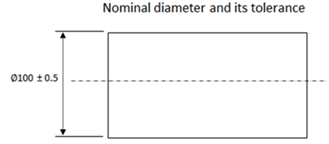
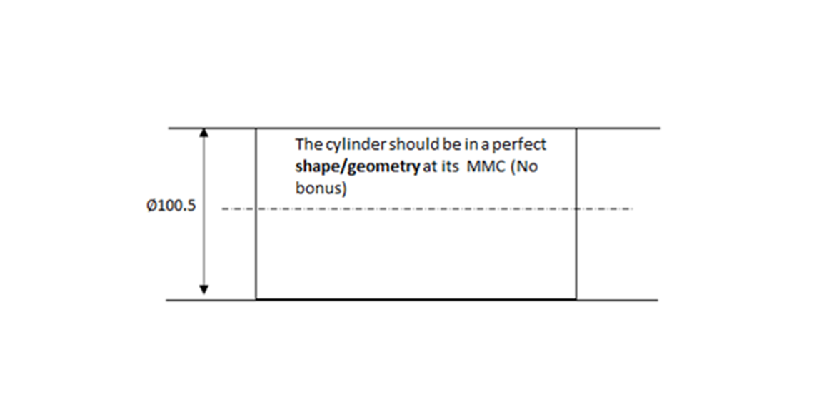
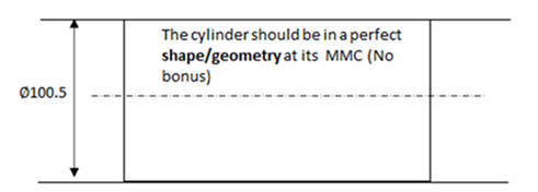
Figure 2 below shows the illustration of why at MMC an external features (cylindrical pin) feature should be in perfect form to still satisfy its function.
In this figure, when the pin is manufactured at its MMC, that is 100.5mm, the cylinder should be in perfect form and no bonus tolerance.
A slightly imperfect form will cause the pin cannot enter its mating hole!
GD&T rule #2
GD&T rule #2: Default condition is Regardless of Feature Size (RFS). This rule means that, by default when no MMC or LMC is specified, the GD&T tolerance is independent of the dimension of the part (feature of size) and there is no bonus tolerance, unlike MMC and LMC modifier.
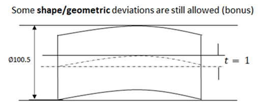
Figure 3 below shows an example when there is bonus tolerance with MMC symbols. When the pin is made smaller than its MMC size, that is, the diameter is <100.5mm, there will be some allowable form imperfections such that the pin still can fit the mating hole.
For example, when the cylinder is produced with diameter of 99.9 mm (still within its “+/- tolerance), hence the cylinder can have a shape deviation (in this case positional tolerance) as much as 100.5-99.9=0.6 mm.
As long as the cylinder (pin) does not have a cylindrical deviation of more than 0.6 mm, then the cylinder (pin) still can be inserted into the hole.
In this case we have 0.6mm bonus positional tolerance. This bonus tolerance has a huge impact n manufacturing and inspection cost!
READ MORE: Good practice guide for designing an assembly and its components
Conclusion
In this post, we briefly discuss the history of GD&T to understand the original and motivation of GD&T in manufacturing and part interchangeability.
GD&T started from the observation of Stanley Parker who observed some rejected parts were actually still can be used and meet its functional requirements.
These implications cause the formation of two GD&T basic rules: Rule #1 and Rule #2.
These two rules have an immense impact on the total cost of manufacturing and inspection process of parts!
You may find some interesting items by shopping here.