Uncertainty estimation of laser interferometry measurements
Length or distance measurement with a laser interferometer has an important application in various engineering and scientific fields.
Length or distance measurement with a laser interferometer has an important application in various engineering and scientific fields. Not only laser interferometer can provide a very accurate length/distance measurement, but also laser interferometer can be used for establishing traceability chain of length measurement to the definition of meter.
Laser interferometer is very common to be used for linear axis calibration and accuracy verification. With laser interferometer, the linear distance errors as well as rotational errors of a linear axis can be quantified.
In this post, the uncertainty estimation of laser interferometer length measurement will be presented and discussed in detail.
Basic working principle of laser interferometer
The basic working principle of laser interferometer is by utilising the interference characteristic of two coherent wave.
The main configuration of a laser interferometer is as follows. A laser interferometer system consists of a laser source, fixed (location fixed/statis) optical elements as reference beam, and moving optical elements as measurement beam.
The laser source can have one or two wavelengths. If the laser source has a single frequency, then the interferometer is called homodyne interferometer. Meanwhile, if the laser source has two frequencies, hence the laser interferometer is called heterodyne interferometer.
The illuminated laser from a source can be polarised or non-polarised. The most common laser interferometer configuration is Michelson interferometer with polarised laser.
Modern and common laser interferometers can have resolution from $10nm$ to $0.1nm$ and can measure distances up to approximately $100m$.
Figure 1 below shows the basic working principle of a laser interferometer as well as a real setup of the laser interferometer. As can be seen from figure 1, the moving optical (retroreflector mirror) elements are placed on the moving part of the axis under measurement. Meanwhile, the beam splitter and reference mirror are placed at a static location (fixed in a stable location).
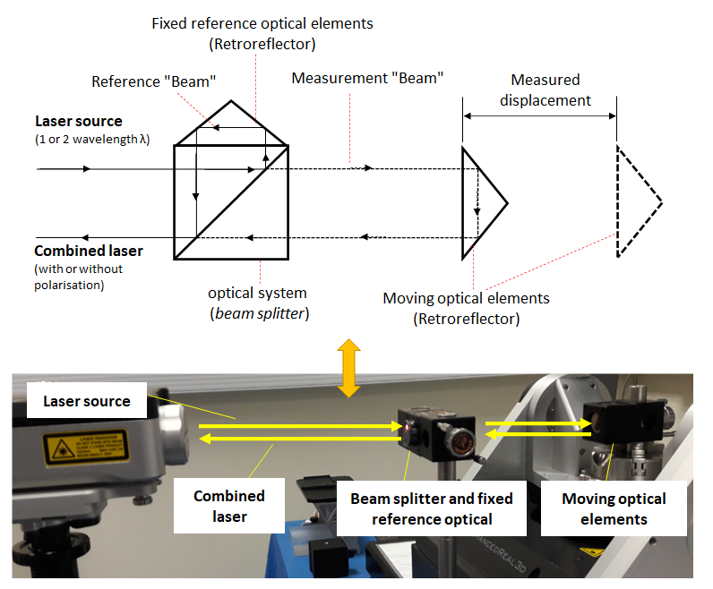
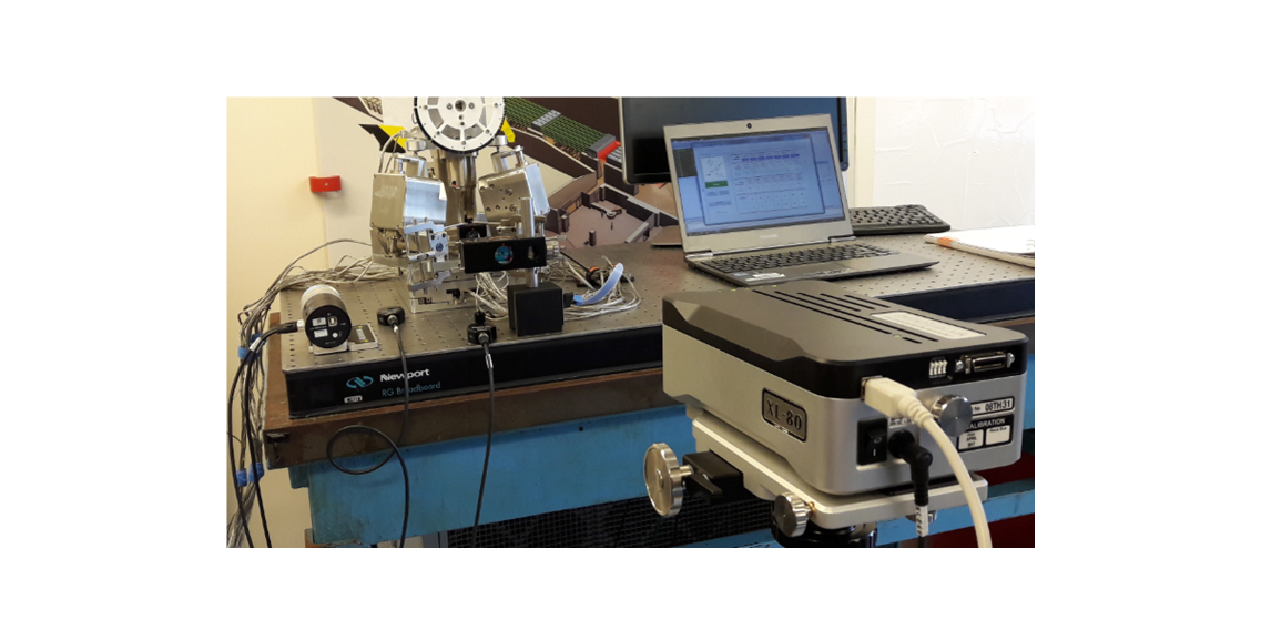
Figure 2 below shows a real example of displacement (length) measurement of the linear axis of a 6-axis parallel kinematic robotics. From figure 2, the moving optical elements of retroreflectors mirror are placed on the moving linear axis of the robot.
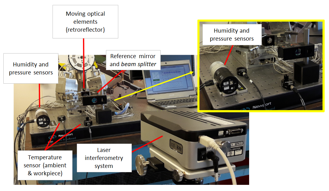
The part temperature $T_{s}$ sensor is placed on the flat table with steel surface very close to the axis. The reasons are that the sensor is too big to be placed on the moving axis and the surface temperature of the flat table is considered equal with the linear axis since they both have been placed in the same room for a long time. that is the temperature has been homogenised.
The humidity, air temperature and pressure sensors are also placed very close to the moving axis under measurement. By placing all sensors close to the moving axis, all ambient variations close to the measured axis will be captured so that representative (effective) wavelength of the laser around the measured axis can be estimated accurately.
READ MORE: Measurement uncertainty estimation: Spreadsheets method
Laser interferometer measurement model and uncertainty contributors
To determine uncertainty contributors for laser interferometer measurement, the model of laser interferometer measurement is the main reference.
The model of distance measurement $d$ by a laser interferometer is formulated as follow:
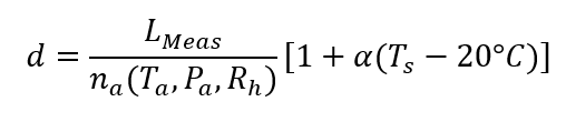
Where $L_{Meas}$ is the distance measurement with a laser interferometer, $n_{a}$ is the refractive index of air, $T_{s}$ is a the temperature of a measure part (commonly made of steel material), $P_{a}$ is the ambient (air) temperature, $RH$ is the ambient (air) relative humidity and $P_{a}$ is the atmospheric (ambient or air) pressure of the environment where the laser interferometer measurement is performed.
From the above laser interferometer measurement model, it can be observed that the final measured distance $d$ is directly affected by the refractive index $n_{a}$ of the ambient (that is air). Based on [1], the refractive index $n_{a}=f(T_{a}, RH, P_{a})$.
This refractive index of air $n_{a}$ will directly affect the laser wavelength used in a laser interferometry. That is, the affected laser wavelength $\lambda _{a}$ then will directly affect the final measurement $d$.
Hence, to have a very accurate distance measurement by a laser interferometer, the measurements of ambient conditions have to be performed to be able to compensate ambient or environmental effects so that an accurate actual wavelength $\lambda _{a}$ of the laser can be calculated [1].
Hence, the main uncertainty contributors for distance measurement by using a laser interferometer are $T_{s},T_{a}, RH, P_{a}$ and the repeatability of the measurement calculated as the standard error (Type A uncertainty).
Regarding ambient or environment related contributors $T_{a}, RH, P_{a}$, there are two ways to determine the sensitivity coefficient of these contributions, they are:
- Based on experimental results published in [1]
- Based on manufacturer specific recommended values (as being applied in [2])
Sensitivity coefficient is the conversion factor from the unit of $T_{a}, RH, P_{a}$, that are not in the unit of length (such as $m$, $cm$ and $\mu m$), into the unit of length (commonly in $\mu m$).
READ MORE: The fundamental concept of metrology
Uncertainty calculation method 1: using sensitivity coefficient values from published experimental results
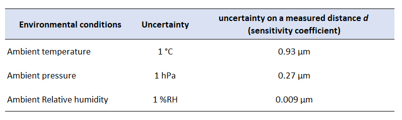
In this method, the sensitivity coefficient determination for ambient-related uncertainty contributors ($T_{a}, RH, P_{a}$) is based on [1]. The sensitivity coefficient to convert the unit of $T_{a}, RH, P_{a}$ to the unit of length is presented in Figure 3 below.
In figure 3, the sensitivity coefficient represents the change of unit length (in $\mu m$) with respect to one unit change in the ambient-related uncertainty contributors ($T_{a}, RH, P_{a}$).
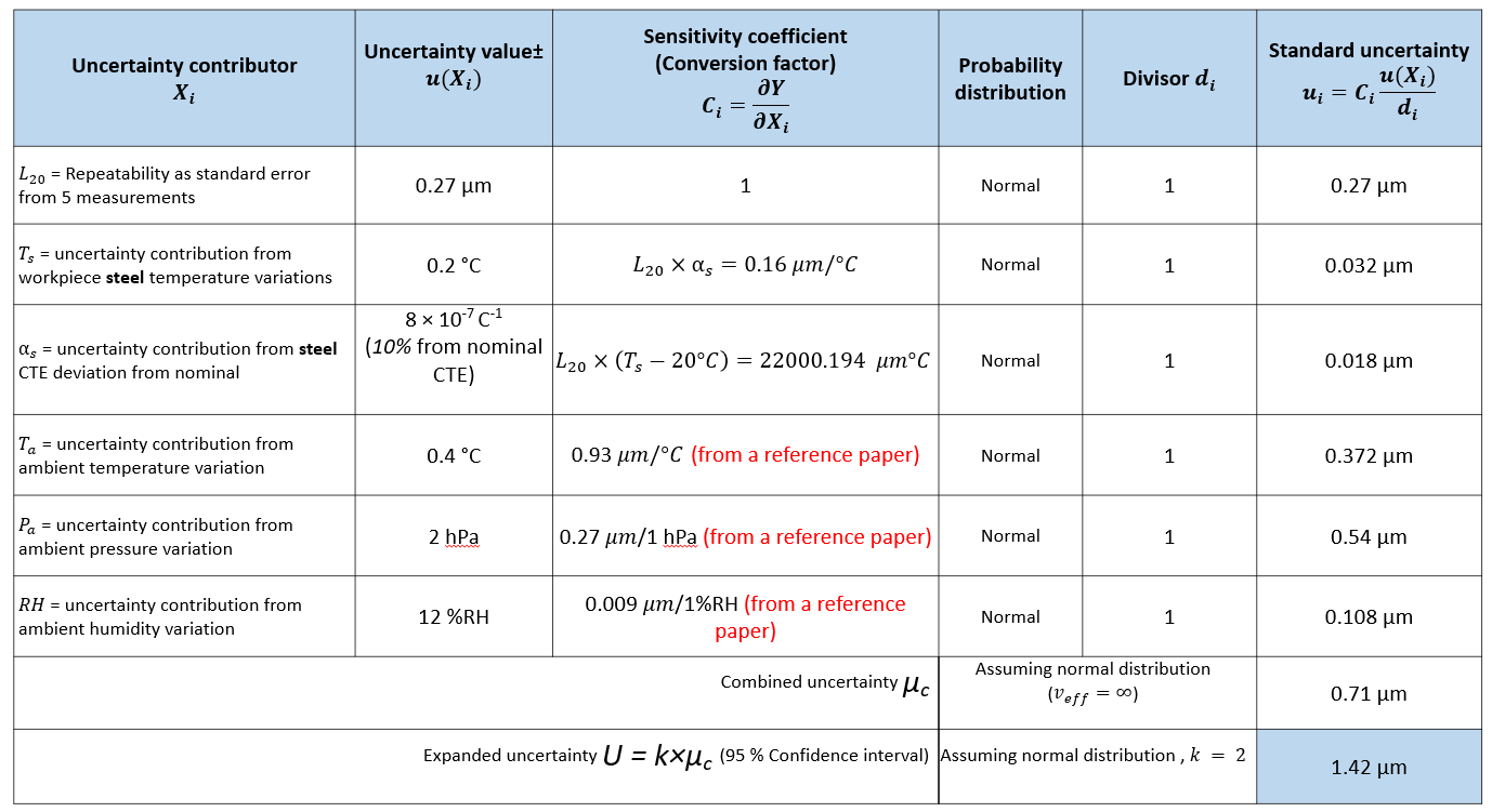
Suppose we are measuring the length of a part with nominal length of $20 mm$ represented as $L_{20}$ by using a laser interferometer having a polarised red laser. The measurement is performed in a temperature-controlled room (environment) with ambient temperature $T_{a}$ of $(20 \pm 0.4)^{\circ} C$, relative humidity $RH$ of $50%RH \pm 12%RH$ and ambient pressure $P_{a}$ of $(1020 \pm 2) hPa$.
The uncertainty of the length measurement is performed using spreadsheet method and is presented in Figure 4 below. From figure 4, from the uncertainty estimation calculation by using spreadsheet method, the combined standard uncertainty is $0.71 \mu m$. Hence, the expanded uncertainty of the length measurement is $1.42 \mu m$
READ MORE: Measurement uncertainty estimations: GUM method

Uncertainty calculation method 2: using sensitivity coefficient values from manufacturer recommended specific values
In this method, another way of determining the sensitivity coefficient for ambient-related uncertainty contributors ($T_{a}, RH, P_{a}$) is based on the datasheet or specification from the manufacturer of the laser interferometer used in a distance (length) measurement.
This uncertainty estimation method has been implemented in [2].
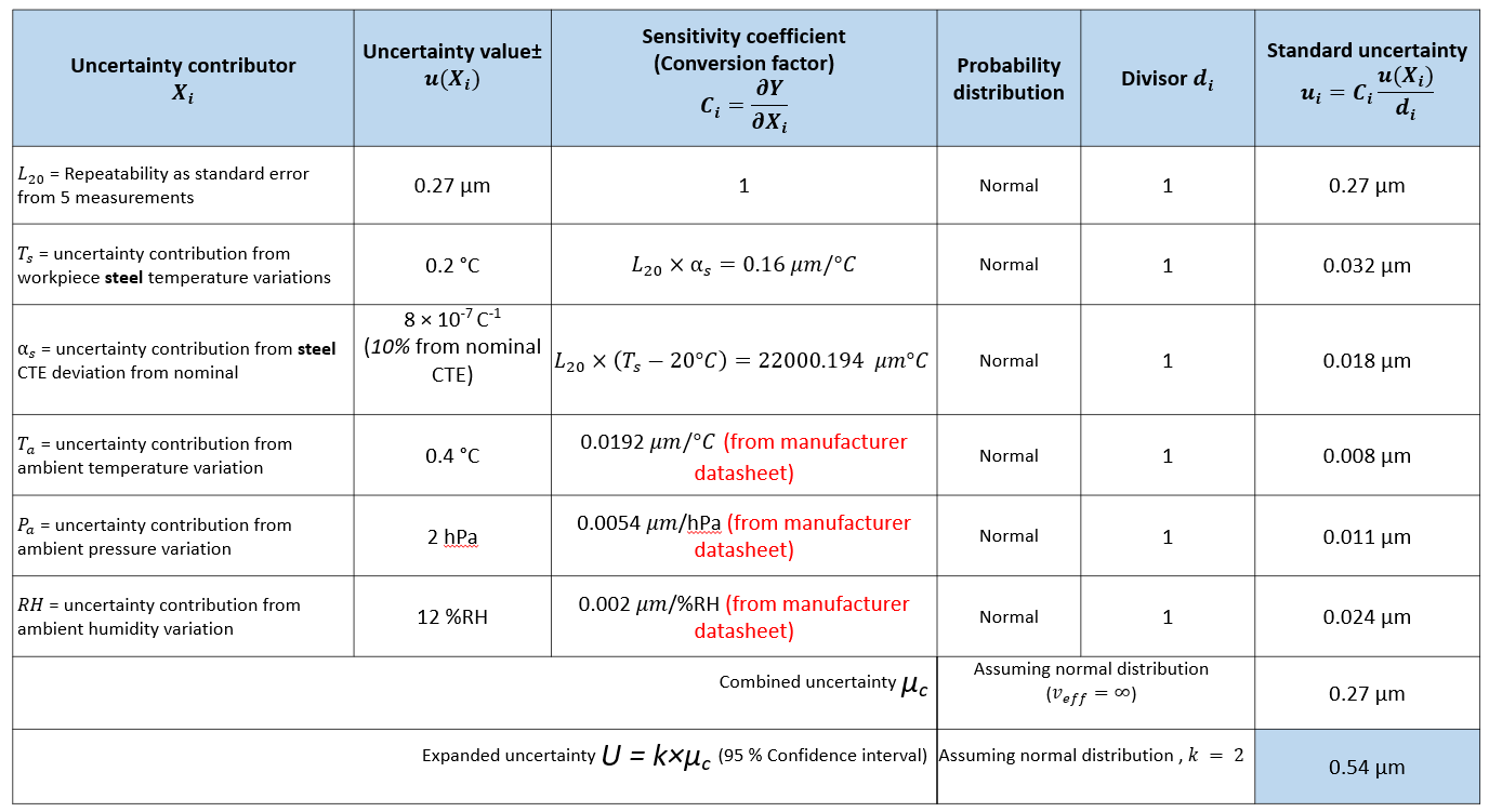
Using the same laser interferometer length measurement example from the previous section, that is the measurement of a part with nominal length of $20 mm$ represented as $L_{20}$ and is performed in a temperature-controlled room (environment) with ambient temperature $T_{a}$ of $(20 \pm 0.4) \degree C$, relative humidity $RH$ of $50%RH \pm 12%RH$ and ambient pressure $P_{a}$ of $(1020 \pm 2) hPa$, different total expanded uncertainty is obtained.
The main reason is that, in this second example, the sensitivity coefficients, used to convert the units of the ambient-related variables ($T_{a}, RH, P_{a}$) to the unit of length (in $\mu m$), are based on values from the manufacturer of the laser interferometer.
By using the same spreadsheet method, the combined standard uncertainty is $0.27 \mu m$. Hence, the expanded uncertainty of the length measurement is $0.54 \mu m$ as shown in Figure 5 below.
The total expanded uncertainty is approximately three times smaller than the uncertainty using the sensitivity coefficient from the published results (explained in the previous section).
The reason is that in this method the manufacturer specifically conducts experiments to obtain the sensitivity coefficient for the specific laser interferometer in use. Hence, the sensitivity coefficient is only valid for the specific laser interferometer made by the manufacturer.
READ MORE: Measurement uncertainty estimations: Monte-Carlo simulation method

Conclusion
In this post, the estimation of measurement uncertainty of laser interferometer length measurement has been presented and discussed.
Important note to remember is that laser interferometer measurements are very sensitive with ambient conditions (humidity, pressure and temperature variations) where measurements are performed. Because these ambient conditions will directly affect the wavelength of the laser and then directly affect the results of length or distance measurements.
For uncertainty estimation of laser interferometer length measurement, there are two methods to determine the sensitivity coefficient for the ambient-related uncertainty contributors. One method is by using values from published experimental results and another way is by using values from provided by the manufacturer of the laser interferometer.
In general, using the sensitivity coefficients from the manufacturer provided values will result in smaller expanded uncertainty estimation. However, these values are only valid for the specific laser interferometer made by a specific manufacturer that provides the sensitivity coefficient values.
References
[1] Bönsch, G. and Potulski, E., 1998. Measurement of the refractive index of air and comparison with modified Edlén's formulae. Metrologia, 35(2), p.133.
[2] Santoso, T., Syam, W.P., Darukumalli, S. and Leach, R., 2022. Development of a compact focus variation microscopy sensor for on-machine surface topography measurement. Measurement, 187, p.110311.
You may find some interesting items by shopping here.