Error compensation for coordinate measuring instrument: introduction and types
Error compensation is an important process to produce an accurate measuring instrument. Any measuring instruments, although inherently constituted by accurate and precise components, always have some degree of error.
Error compensation is an important process to produce an accurate measuring instrument. Any measuring instruments, although inherently constituted by accurate and precise components, always have some degree of error.
Error always exists on measuring instruments and can be from two main sources: part geometrical error due to manufacturing process imperfections and error during the assembly process of the instruments (assembly error) [1].
Accurate measuring instruments leverage and implement error compensation systems. By implementing the error compensation systems, errors on the instrument can be significantly reduced if not eliminated.
By reducing error, the accuracy level of the instrument can be significantly increased.
Error compensation commonly performed by the manufacturer of measuring instruments after the instruments have been assembled and before the instruments are shipped to customers.
In general, error compensation is divided based on what method is used and based on when the compensation is applied.
Error compensations based on method are hardware-based and software-based compensation.
Meanwhile, error compensations based on implementation time are real-time and offline (non-real time) compensation.
READ MORE: Ten types of dimensional and geometrical measurement error

Why error compensation?
In the past, precision measuring instruments were very often made from very high precision components. The main drawback of this method is that since the components are very precise and accurate, the production cost of the whole instrument becomes very high.
Because, to make high precision components, long and repetitive machining processes, such as milling, boring and polishing, are required. These processes are usually for finishing component to produce and achieve accurate and precision components.
The precision and accuracy of a measuring instrument does not only depend on the precision of its constituted parts, but also depends on how the parts are assembled together (the accuracy of the assembly process) to make the instrument as well as other systems.
For example, the accuracy and precision of a coordinate measuring machine (CMM) measurement depends on the accuracy of the CMM and the accuracy of other systems, such as the probing system of the CMM.
In addition, other factors that affect the accuracy of measuring instruments are, such as, electronic systems and environmental effects, such as temperature variation and vibration noises.
Since the production cost of measuring instruments using high precision and accurate part is very expensive, the selling price of the measuring instruments will be very high and is not economically competitive in the market.
Hence, error compensation is a way to improve the accuracy of measuring instruments without focusing on using very accurate parts, instead by reducing (compensating) the errors of the instruments as long as the errors are systematic [1].
There are two different concepts that have to be understood: error avoidance and error compensation.
Error avoidance is a process to make the geometry of a component or part as accurate as possible. This error avoidance strategy requires high cost since producing accurate components or part requires high accurate machinery and long manufacturing process time.
Error compensation is a process to quantify and to separate an error obtained from a measurement or measured signal so that the quantified error can be added/subtracted from the measurement or signal. Hence only the original measurement or signal will be obtained (without the error component).
With this error compensation strategy, a high accuracy measuring instrument can be obtained with significantly lower cost compared to the error avoidance strategy.
One important aspect to be understood is that error compensation can only be applied to compensate systematic error (such as geometrical error of components). systematic error is a type of error that is constant (repeatable) and predictable (can be modelled analytically or empirically).
The main purpose of error compensation is to produce high accurate and precision machines with relatively low cost.
Meanwhile, random error cannot be compensated because it cannot be predicted. Random error can only be “compensated” by using closed-loop real-time control strategy. That is, the error is measured in real time and then compensated.
A measuring instrument should have high accuracy. A measuring instrument can be considered as being able to measure a part effectively and efficiently only if the accuracy level of the instrument is one magnitude higher than the accuracy of the measured part.
For example, to measure the roundness of a cylinder with nominal value of 0.05mm. Hence, the maximum roundness error of the spindle of a measuring instrument used to measure the roundness should be 0.005mm or less.
If the roundness error of the spindle of the instrument is high, for example 0.1mm, then the roundness measurement results will not be reliable, that is meaningless. Because the measured roundness is the roundness from the instrument instead of the roundness from the measured cylinder (see GR&R test).
READ MORE: Understanding measurement model, systematic error and random error
Error compensation based on compensation method: Software and hardware
In real situations, any motion systems will achieve a final position that is deviated from its original motion commanded by a controller. The difference between the commanded position and final achieved position is called position error.
This position error needs to be compensated to improve the accuracy of a motion stage and finally the machine or measuring instrument using the motion stage.
In this section, error compensation based on the compensation method will be discussed, they are software and hardware-based error compensation.
Error compensation based on software is often called as numerical error compensation.
In general, these software and hardware error compensation require the mathematical model of the kinematics of a machine or instrument. From these mathematical models, errors on each actuator possible positions (within the working or measuring volume) can be mapped and the result is called error map.
Error map is a function that can predict the error at each possible position of the motion system in a machine given a set of inputs, such as nominal or commanded positions.
Hardware-based error compensation is a process to compensate errors on actuator positions by implementing a hardware system on the actuator.
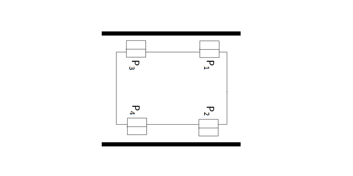
Figure 1 below shows an example of the use of hardware-based error compensation. In figure 1, a linear motion stage is shown that travels across a guide.
Of course, in its implementation or application, both the stage and the guide have geometrical error due to their manufacturing process imperfections.
In this case, if the solution to reduce the error is by applying finishing process on both parts to achieve a higher geometrical accuracy than their current states, then the solution is called error avoidance instead of error compensation.
With error compensation solution to reduce the error, a mathematical model that maps the error of the linear motion stage positions is used to quantify errors on each possible positions error with respect to the guide.
Then, a hardware system is applied on the linear motion stage such that if there is a position error on the motion stage position, then the hardware system will compensate the position (to follow the commanded position) to reduce the error. The error compensation mechanism is by adjusting and maintaining the gap between the motion stage and the two-wall of the guide (see figure 1).
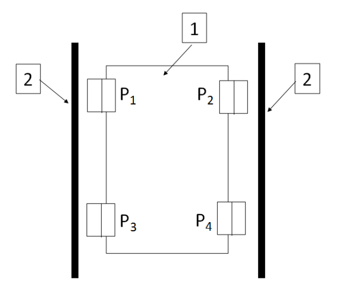
In figure 1 above, there are four piezo elements mounted on the motion stage, that are P1, P2, P3 and P4.
P1 and P3 are piezo-element actuators that control the stage distance with respect to the guide wall at the left side. Meanwhile, P2 and P4 are piezo-element actuators that control the stage distance with respect to the guide wall at the right side.
When the motion stage (number 1 in figure 1) moves to a certain position, the straightness error of the motion stage (obtained from its error map), will be compensated by the piezo elements. If from the error map has an error toward the left guide wall, then piezo element P1 and P3 will push the stage back to the right direction to correct the stage position at that location and otherwise.
Hardware-based error compensation requires higher cost than software (numerical) compensation.
Software-based (numerical) error compensation is an error compensation process by correcting position errors (obtained from an error map) at a specific location by correcting a given motion command by adding the negative of the error on that location.
This error compensation does not apply any hardware placed on the actuator of a motion system. Instead, this method only uses an additional software control system to modify a given command position to compensate an error on that specific location based on the error map of the motion system.
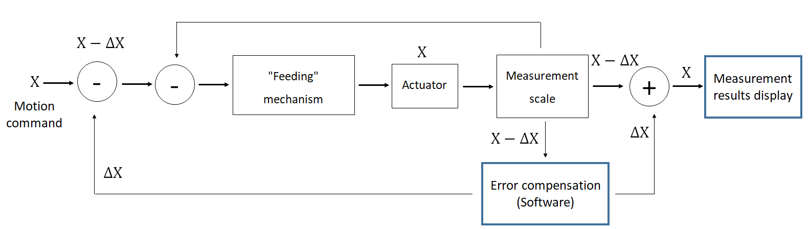
Figure 2 above shows the architecture of software-based (numerical) error compensation. In figure 2, it is shown that a numerical control system commands an actuator to move as many as $X$ position.
From this command, a feeding mechanism move the actuator to move as many as $X$ position. However, in reality, the actual position of the actuator is not exactly as many as $X$ position because there is an error $\delta X$. Hence, the actual position of the actuator is $X+\delta X$.
With software error compensation, the error $\delta X$ at the actuator position can be obtained from the error map of the actuator of a motion system. From this known error, the software will give feedback to the control system to correct or modify the given position command as many as $\delta X$.
Hence, the actual position of the actuator will be $X+\delta X - \delta X=X$. That is, the actual actuator position will be very close (if not equal) to the commanded position.
However, software error compensation has a limitation. That is, this compensation can only be applied to machines with point position motion system, such as turning and milling machines and tactile coordinate measuring machine (CMM). In other word these machines only interact with a part at one point, or location on a part, at a time.
For other types of machines, such as drilling machine and non-contact (optical) CMM that interact with or probe a surface at multiple locations (areal), it is difficult to compensate positional error from the numerical control system of the machines [1].
READ MORE: Error sources on coordinate measuring machine (CMM) measurements and environment control
Error compensation based on implementation time: real-time and off-line
Error compensation based on implementation time are divided into two types: real-time and off-line (non-real time) error compensation.
In principle, off-line error compensation can only be applied for systematic error. Meanwhile, real-time error compensation can be applied for both systematic and random error correction, although the implementation very often is more difficult compared to off-line error compensation.
Reasons of why real-time error compensations is that real-time error compensation deals with non-linear noises in real situations that are difficult to model, except statistically. For example, noise from temperature variations, environmental noise, atmospheric pressure variation and dynamical effects from the motion of components of a motion system.
Off-line error compensation is implemented by storing the error map and/or mathematical model of an instrument in a computer memory. These systematic errors are quantified before via, for example, a calibration process.
For example, the position error of a CMM can be quantified by measuring a calibrated gauge-block or reference artefact. The difference between the measured value by the CMM and the nominal value of the gauge-block or artefact is the error at that length or location.
Other than measuring gauge-block or artefact, another common way to reconstruct the error map of an instrument is by using a laser interferometry. With laser interferometry, a motion stage is move from its smallest to largest position and the position is also measured by the laser interferometry. The difference between the laser and motion stage measurement is the position error at their corresponding commanded location.
This process is repeated for all possible measuring position within the measuring volume of the CMM. From this process, the error map of the CMM can be obtained.
By using this error map, any commanded locations of the CMM will have their corresponding error value in the error map. And then, off-line error compensation can be applied by compensating the error value into the control system to modify the commanded position.
Reconstructing error map by measuring gauge blocks or artefact or by using laser interferometry requires long time and high operator resources.
Another alternative to build error map is by developing the kinematic model of an instrument. By having this kinematic model, only errors at several position needs to be quantified and by using the model other errors in the measurement volume can be predicted.
Real-time error compensation is an error compensation that is applied when a measurement is carried out. With real-time error compensation, a measurement or position error is quantified at that measurement time [2].
In general, the error is defined as the difference between the commanded (by a numerical control system) position and actual measured position.
Hence, a closed-loop control mechanism is instrumental for real-time error compensation. This closed-loop feedback is required by the control system to know the error at that position and then compensate by moving the motion stage to the expected (commanded) position.
The challenge of implementing real-time error compensation are as follows. The compensation has to deal with non-linear errors by implementing a sophisticated sensors systems and control algorithm. Hence, the required implementation cost will be high due to the need of the sensor systems.
However, the rewards by implementing real-time error compensation are that both systematic and random error can be corrected. And hence, the accuracy of an instrument can be improved significantly.
READ MORE: Coordinate measuring machine (CMM): An introduction, types, considerations and applications
Conclusion
Error compensation is a method to correct the error of a measuring instrument or other machines with motion systems. The idea is to reduce the production cost of a high accuracy and precision instrument and machine.
Because, the systematic error from the geometrical inaccuracy of parts constituting an instrument or machine can be quantified and then compensated to get an accurate positioning and/or measurement result.
There are types of error compensation. Based on compensation method, error compensation is divided into hardware and software (numerical) error compensation. Meanwhile based on compensation time, error compensation is divided into real-time and off-line error compensation.
The most challenging error compensation is real-time error compensation as this compensation requires both software and hardware (feedback sensors) implementations. However, real-time error compensation can correct both systematic and random error.
Reference
[1] Hocken, R.J. and Pereira, P.H. eds., 2016. Coordinate measuring machines and systems. CRC press.
[2] Huang, P.S. and Ni, J., 1995. On-line error compensation of coordinate measuring machines. International Journal of Machine Tools and Manufacture, 35(5), pp.725-738.
You may find some interesting items by shopping here.