Error sources on coordinate measuring machine (CMM) measurements and environment control
A coordinate measuring machine (CMM) is a complex measuring instrument. Hence, there are many error sources that cause the degradation of a CMM measurement accuracy and the increase of the uncertainty of the CMM measurement results.
A coordinate measuring machine (CMM) is a complex measuring instrument. Hence, there are many error sources that cause the degradation of a CMM measurement accuracy and the increase of the uncertainty of the CMM measurement results.
To be able to optimise the efficiency and efficacy of CMM measurements, we need to know and understand error sources related to the CMM measurements.
In this post, we will discuss the main error sources for CMM measurement.
(Note: All 3D illustrations were created by using a CATIA 3D modelling software)

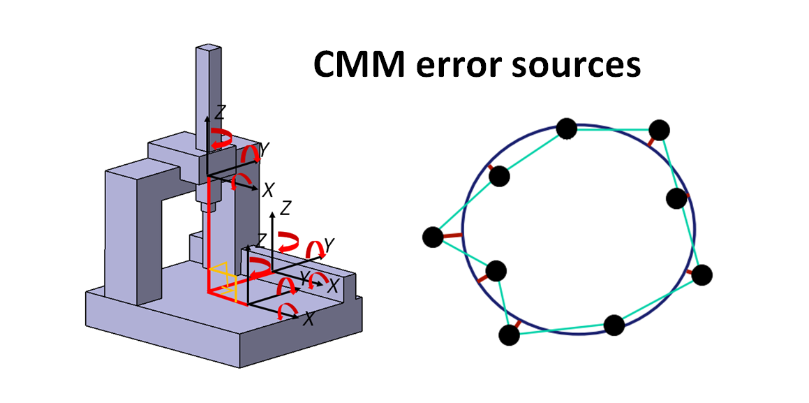
CMM measurement error sources
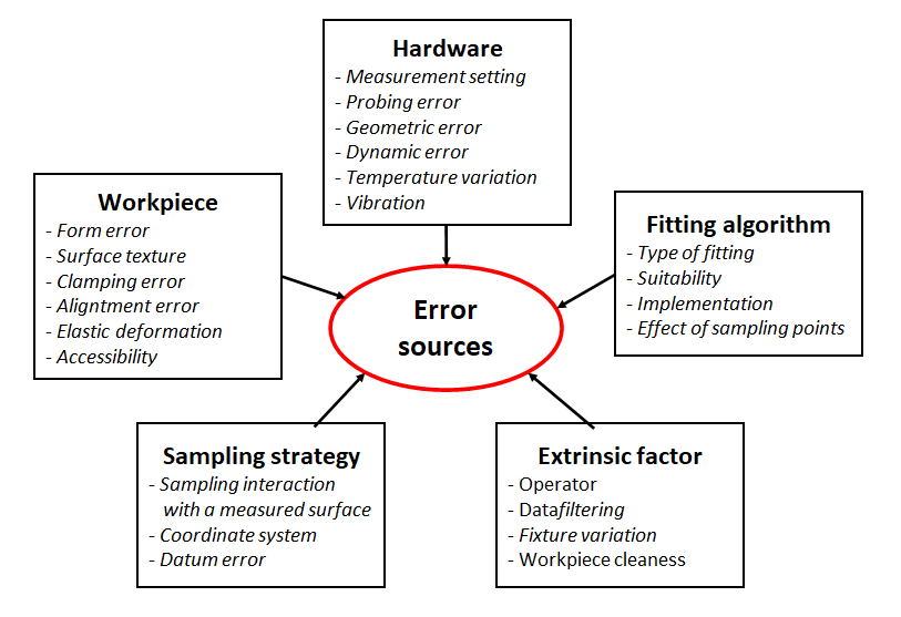
The main error sources for CMM measurement are classified into five categories: hardware (CMM machine), measured workpiece, sampling strategy, fitting algorithm and extrinsic factors.
Figure 1 below shows the five main error sources and their examples that affect CMM measurements. From figure 1, it can be observed that the error sources do not only depend on internal CMM property but also external factors.
Since there are many possible error sources on CMM measurements, we need to have a good procedure when performing dimensional and geometrical measurements with CMMs.
Let us discuss further each main error sources for CMM measurements.
READ MORE: General procedures to operate a tactile coordinate measuring machine (tactile-CMM).
CMM Measurement error due to hardware
Error sources from hardware include errors that are related to CMM machine components, such axis, motor, bearing and structural elements, as well as measurement process parameters, such as measurement speed.
Some lists of errors related to hardware are probing error, CMM geometric error, dynamic error, temperature variation-induced error, vibration-induced error and measurement process parameter related errors.
Some examples of measurement process parameters are the determination of the speed of motion axes to reach features on a measured part. This speed determination is directly related to the dynamic error of a CMM machine.
The dynamic errors are affected by the acceleration and deceleration of the CMM axes.
In principle, the determination of the speed of the motion of CMM axes is obtained from a trade-off analysis between measurement time and measurement accuracy.
In general, measurement time is inversely proportional to measurement accuracy due to the dynamic effect of CMM structures. The shorter the measurement time (higher measurement speed), the lower the measurement accuracy will be, and otherwise.
Probing error includes any errors that are related to the probing system of a CMM. For example, the accuracy of the displacement sensor on a probing head, inaccuracy of a stylus tip geometry due to its manufacturing imperfection (in actual condition, a stylus tip shape is not perfectly sphere!).
The temperature variation in a measuring room directly affects the thermal expansion of the structure of a CMM. The reason is that all materials will have a coefficient thermal expansion (CTE) that defines how large the expansion (or shrinkage) when the materials are at temperature other than 20 degree C. Hence, a CMM component will expand when it is at above 20 degree C and will shrink if it is below 20 degree C.
Vibration on CMM structure due to the acceleration and deceleration of the CMM axes also significantly affect CMM measurement error. This vibration will disturb the position reading on the measuring (encoder) scale.
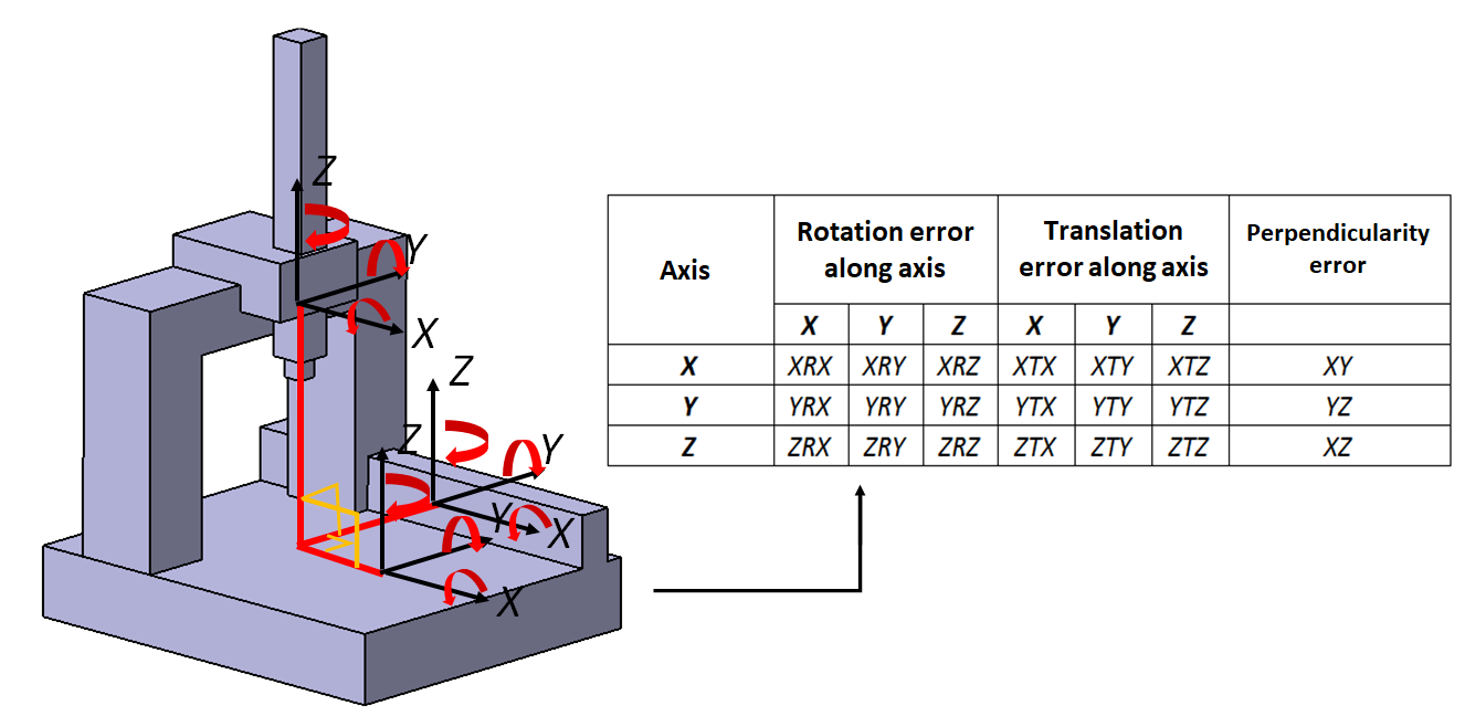
Geometric error is the geometrical deviation from the nominal dimensions of components constituting a CMM machine.
For 3-axes CMM, there are a total of 21 relevant geometric errors. Figure 2 below shows the 21 axes error applied to 3-axes CMMs.
The 21 errors are: 6 axes errors (scale error, 2 straightness errors, 3 rotational errors). Because there are 3-axes, hence there are 18 errors from the 3-axes. The other 3 errors are the error of perpendicularity between 2 axes: XY, XZ and YZ.
READ MORE: The probing system of tactile-CMM: The history, configuration and mechanism.
CMM Measurement error due to workpiece
Error sources that are related to workpiece are form error (geometric errors such as flatness, cylindricity, position and run-out error), surface texture related error, clamping error, alignment error, elastic deformation and accessibility issues.
Errors from a workpiece will directly translated to CMM measurement errors as the form error will be capture by the probing system of the CMM. That is, the form error of the workpiece increases the uncertainty of the CMM measurement.
In addition, the level of surface roughness will also affect the accuracy level of CMM measurements.
Errors from the clamping that hold a measured workpiece also directly contribute to the total error of a CMM measurement. High clamping force will cause a workpiece that is held by the clamp will be elastically deformed, or in the worst case will be plastically deformed.
Alignment errors commonly happen because a CMM operator cannot correctly define a workpiece coordinate system (WCS) and/or cannot correctly select the location where to put the WCS.
CMM Measurement error due to sampling strategy
Sampling strategy is also one of the main error contributors for CMM measurements.
Errors related to sampling strategy include sampling interaction with the form of a measure workpiece, coordinate system errors and datum or reference errors.
The interaction between sampling strategy and a measured part means that, for geometrical (GD&T) verifications, the location of sampled points should cover critical areas, which have the largest form deviation, on the part.
The reason is that, for geometrical verification, the form (for example, flatness, cylindricity, position, and run-out) errors are determined only by the maximum deviation on a measured surface. Other areas that do not have the largest deviation will not contribute to the final geometrical deviation calculations.
If sampling points do not cover the critical area (with maximum geometrical deviation) on a measured part. Then, no matter how many sample points we take, the final geometrical measurements will not be correct since the measured deviation will not represent the real geometrical form of the part. Because there will be biases errors.
Datum error is very relevant when a geometrical feature with a relation with respect to other geometries is measured. Some examples of related geometrical features are perpendicularity, parallelism, position and run-out.
To perform geometrical measurements for related features, the selection and determination of a datum for the measurement is very critical. If the selected datum is not correct or there are geometrical deviations on the selected datum feature, the geometrical measurement of the related-feature will be significantly degraded (large error).
READ MORE: Sampling strategy for coordinate measuring machine (CMM) measurements.
CMM Measurement error due to fitting algorithm
Errors related to fitting algorithm are types of fitting (for example, least-square or minimum-zone fitting), suitability of the use of algorithm, fitting algorithm implementation and number of sample points for fitting process.
There are various types of fitting algorithm. Every different fitting algorithm (for example least-square fitting versus minimum-zone fitting), when applied to the same sampled points or data, will give different calculated geometrical parameter estimations.
A correct selection of which fitting algorithm we need to use is very critical. For example, when we want to perform a sphere geometrical fitting to points, but when we select between least-square or minimum-zone fitting, it will give different sphere centre and radius!
The number of points used for fitting algorithm also significantly affects the fitting results.
For least-square fitting, ideally the more points we have (covering the major part of a nominal geometry to fit) the better the fitting accuracy. Because the more points used, the more averaging effects we will obtain from least-square fitting algorithm. Hence, error due to noise from the points can be reduced.
For example, of least-square fitting is to fit a plane. Mathematically, to define a plane, we just need three points. However, if we only use three points, there will be no averaging effects from the fitting process and only a small error on one point will lead to significantly wrong plane fitting.
For minimum-zone fitting (the common fitting algorithm used for GD&T verification), basically we just need few points that will define final fitting results for form deviation estimation, such as flatness.
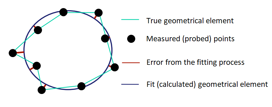
Figure 3 below shows elements that are involved during a fitting process. The elements are sampled points, resulted geometrical element from a fitting process, true geometrical element and the error from the fitting process.
Fitting error is defined as the orthogonal distance from sample points to the geometrical element from a fitting process. This fitting error will significantly contribute to the total error of CMM measurements.
CMM Measurement error due to extrinsic factor
Extrinsic factors include factors that are non-technical but significantly also contribute to CMM measurement error.
Errors considered as extrinsic factors include operator error (such as wrong measurement procedure or steps, unskilled operator), data filtering error (error due to wrongly select a filter or incorrect filtering procedures), fixture variation and cleanliness of a measured workpiece. These extrinsic factors, although seems to be simple, in industry we can find many cases of large CMM measurement errors due to these factors.
Sufficient knowledge for CMM operators or users is required to avoid those errors due to the extrinsic factors.
It is important to invest on training for operator to upskill them so that they have basic knowledge of measurements and CMMs and they can avoid CMM measurement errors due to extrinsic factors.
- Bosch Electric Grass Trimmer- Small and easy-to-handle and best seller electrical grass trimmer.
In addition, not only knowledge about basic measurements and CMMs, but also knowledge about GD&T, fixturing and how to correctly operate CMM machines need to be thought to CMM operators.
The correctness of an operator to place or position a workpiece on a CMM table, to clean the surface of the workpiece and to define CMM-part alignment, datum and measurement procedure with the CMM is very critical to have a good CMM measurement with minimal errors.
The selection of correct procedure or steps for geometrical fitting and data filtering processes (selected on the software of a CMM machine or other third-party software) that are conducted by a CMM operator is very important.
All of the knowledge mentioned above require a serious training for an operator to be able to efficiently and effectively operate a CMM machine for dimensional and geometrical measurements.
Temperature effect on CMM measurements
Temperature variation, both from environment and CMM machine, has a significant effect on CMM measurement accuracy. Commonly, temperature variation very often is the cause for the decrease of CMM repeatability.
Because any materials of a CMM structure have a specific coefficient thermal expansion (CTE) that defines how the structure will expand or shrink following an increase or decrease of temperature.
Figure 4 below shows details of components or factors that contribute to the total error of CMMs due to temperature variation.
In figure 4, we can observe that the total error due to temperature variation comes from three parts of CMM measurement processes. They are error due to temperature effect on a measured workpiece, on metre scale (encoder scale) and on CMM frame.
From these three temperature effects from measured workpiece, encoder scale and CMM structure, they can be further categorised to be caused by uniform temperature and non-uniform temperature.
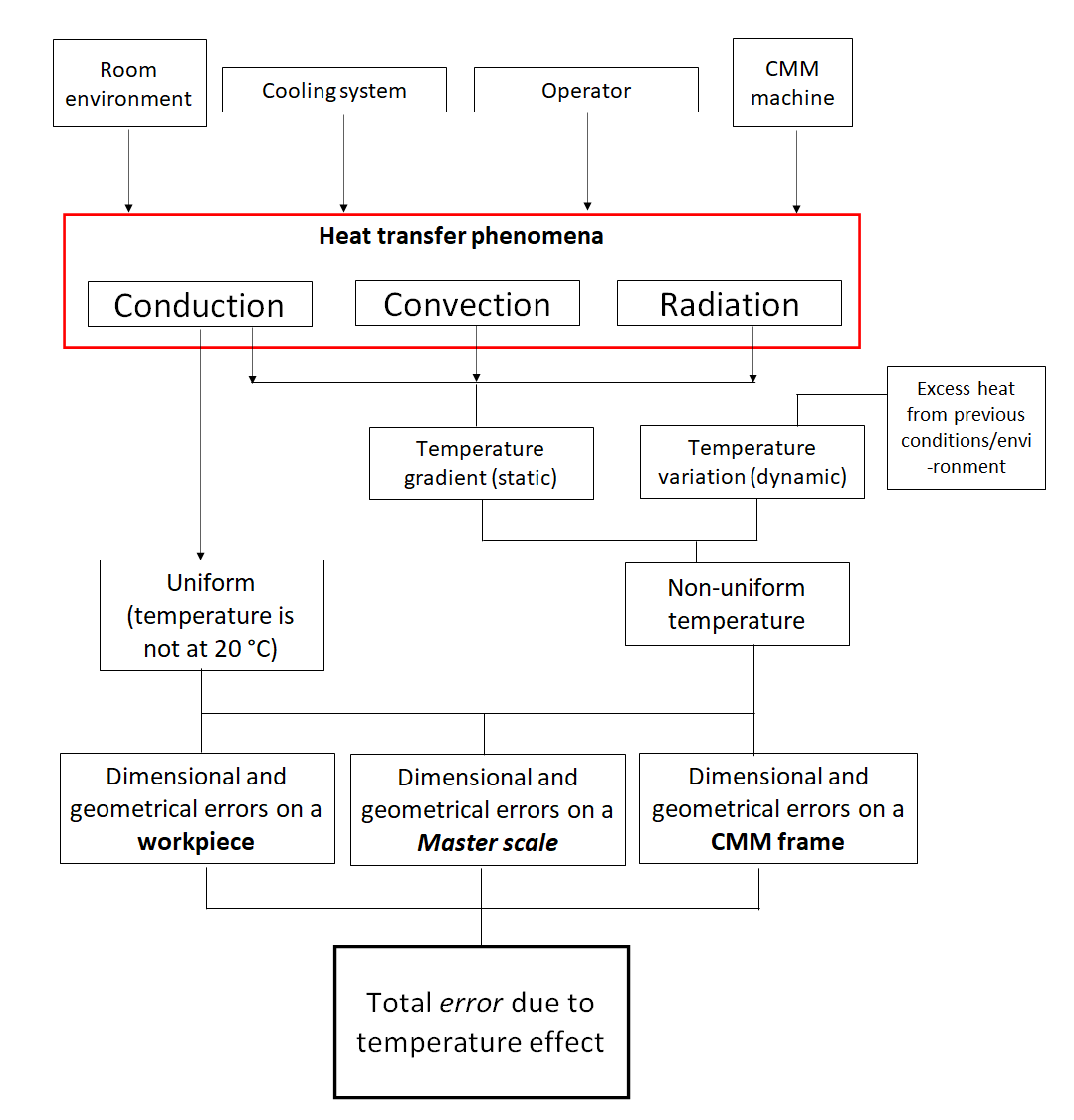
From figure 4 above, the effect of uniform temperature is caused by conduction heat transfers. Meanwhile, the non-uniform temperature effect is due to the combination of conduction, convection and radiation heat transfers.
The uniform temperature effect is easier to control than the non-uniform effect. Because the uniform temperature effect can be easily predicted via a mature mathematical model. The effect of uniform temperature on the expansion (or the shrinkage) of the dimension of a workpiece, master scale (encoder) and CMM frame can then be predicted as well.
The uniform temperature effect on the dimension of a workpiece, master scale and CMM frame is difficult to control. Because the convection and radiation heat transfer effects are difficult to model and predict.
The main sources of the non-uniform temperature effectare temperature gradient, temperature variation and the excess heat from previous conditions or environment.
In figure 4 above, the main sources of heat that affect measurement processes are classified into four groups:
- Heat from a measuring room
- Cooling system of a measuring room
- Heat from the temperature from an operator’s body
- heat from a CMM machine
The heat from a measuring room or environment can be generated from, for example, production machines at or close to where the measurement process is performed. Another example is from the exposure of sunlight to the measuring room via windows.
The cooling system of the measurement room can significantly control the temperature stability on the measuring room as well as to set the room temperature to be constant at around 20 degree C.
The temperature from the body of an CMM operator can not be neglected. Because the normal temperature of a person is about 36 degree C. This values is far from the ideal measurement temperate at 20 degree C.
The heat from a CMM can be from the friction between moving components on the CMM (such as motion axis bearing, etc), heat generated from electrical components on a CMM and heat generated from the electrical motors on a CMM.
All of the above-mentioned heat sources will interact with a measurement process via conduction, convection and radiation heat transfer mode.
Index of thermal error: The contribution of thermal error to the tolerance value
Index of thermal error is an index that estimates the error contribution from thermal effects with respect to the tolerance of a nominal dimension.
The index is a total sum of the linear expansion of a workpiece and measurement scale (encoder scale) of a CMM machine, thermal drift of the CMM and the uncertainty of the coefficient thermal expansion (CTE) of the workpiece and measurement scale.
A measurement process, such as for dimensional measurement, calibration or performance evaluation, will be considered as valid only if the value of the thermal error index has an acceptable value. That is, an acceptable value can be determined from a chosen policy, such as 5% or 10% or 20% from the total tolerance value.
An application example for thermal index error is as follow.
A workpiece made of aluminium with a length of $500 mm \pm 45 \mu meter$. The length is measured at a room with temperature at 24 degree C $\pm$ 2 degree C. The thermal expansion coefficient (CTE) of the aluminium is $24 \mu m ^{-1} C^{-1}$ (11 ppm). The CMM machine has a thermal drift of $2.5\mu m$. There is no thermal error correction applied on the measurement process.
Hence, the thermal error index for the measurement process is calculated as follow:
- Combined thermal expansion of the workpiece and measurement scale:
$L \times \Delta CTE \times \Delta T=0.5 \times 12.5 \times (24-20)=25 \mu m$
- Uncertainty from the CTE of the measurement scale made of steel (assumed to be 10%):
$L \times CTE steel \times 10\% \times \Delta T=0.5 \times 11.5 \times 10\% \times (24-20)=2.3 \mu m$
- Uncertainty from the CTE of the workpiece mad of aluminium (assumed to be 20%):
$L \times CTE aluminium \times 20\% \times \Delta T=0.5 \times 24 \times 20\% \times (24-20)=9.6 \mu m$
- Thermal drift = $2.5 \mu m$
- Hence, the total thermal error $E=25+2.3+9.6+2.5=39.4 \mu m$
Hence, the thermal error index for the measurement process is the ratio between the total thermal error and the tolerance, that is:
$\frac{E}{T}=\frac{39.4}{45}=87.5 \%$
If the operator applies thermal error corrections from the workpiece and measurement scale, then the thermal error index becomes $14.4/45=32\%$
From here, we can observe that by applying thermal error correction, hence the error contribution of the thermal effect can be significantly reduced.
Environment control to reduce measurement error
As has been discussed before that controlling the environment where a measurement is performed is very important.
The main aspects to control related to the environment of measurements are temperature variation, humidity, dust, vibration and sound noise level.
For thermal variation effect, it has been very clearly explained in the above section. That is, temperature variation will directly affect the length of components.
Humidity will significantly affect measurement processes that use laser interferometer. Because humidity will affect the refraction index of air where the laser travels and will affect the laser wavelength. The change of the laser wavelength will change the calculated length as well.
Vibration will degrade a measuring process especially for measurement at sub-micrometre or smaller scale. For example, vibration will affect the pre- and post-travel of the probing system of a CMM.
High sound noise will cause a high-frequency vibration on the components of a CMM used for measurements.
The temperature of a measurement room can be controlled by monitoring aspects such as: the flow direction of air, the inlet and outlet of the air flow, the speed of the air flow, the temperature control system in the room and the location of temperature sensors placed inside the room.
To mitigate vibration, there are three main strategies to follow: identification and reduction of vibration sources, isolation of the vibration sources and isolation of a CMM machine for the vibration sources.
Vibration can be controlled with either or both passive or active control mode. Passive vibration control is suitable for high-frequency vibration isolation. Meanwhile, active vibration control is suitable for low-frequency vibration isolation at < 10 Hz.
Conclusion
In this post, the main sources of error for CMM measurements have been presented.
The error sources many of them are also relevant for other dimensional and geometrical measurement by using other instruments that are not a CMM.
The main error sources are from CMM hardware, measured workpiece, sampling strategy, extrinsic factors and fitting algorithm.
These main error sources directly contribute to the measurement error of CMMs. Discussions on mitigation of these errors are also presented.
Finally, thermal index error to quantify how much contributions of CMM measurement errors from thermal effect are and environmental control to reduce measurement CMM errors are also presented and discussed.
You may find some interesting items by shopping here.