Part-alignment procedure on coordinate measuring machine (CMM) for dimensional and geometrical measurements
Part-alignment is a compulsory process that needs to be performed for CMM measurements. This process is performed right after the qualification process of CMM probing system. Only after part-alignment is performed, dimensional and geometrical measurements by a CMM can be carried out.
Part-alignment is a compulsory process that needs to be performed for CMM measurements. This process is performed right after the qualification process of CMM probing system. Only after part-alignment is performed, dimensional and geometrical measurements by a CMM can be carried out.
The main purpose of part-alignment process in CMM measurement is to construct the coordinate transformation chain from the machine coordinate system (MCS) of a CMM to the work-piece coordinate system (WCS) on a measured part.
After the transformation chain of coordinate system from a MCS to WCS is established, the coordinate reference for CMM measurements can be moved to WCS coordinate system.
The main advantage of using WCS coordinate system for measurement is that measurement errors due to part placement and fixturing errors (even in micrometre scale) can be avoided.
The reason is that in reality, does not matter how precise we place our part on a CMM table (even with the most expensive fixturing system) for measurement, at micro- or sub-micromere-scale, the part has a movement and deviate from its intended position due to, for example, too large fixturing force. That small movement will be significant from a MCS point of view, but not that significant from a WCS point of view.
Figure 1 below shows the illustration of part-alignment process on a CMM. In figure 1, the transformation chain of coordinate system from a MCS to WCS is established with the part-alignment process.
In other words, part-alignment can be viewed as the way a CMM knows the precise and actual position and orientation of a workpiece to be measured that is placed on the CMM measurement table.
Note that to understand the part-alignment process in CMM measurements, knowledge about homogenous matrix and its operation, and coordinate transformation systemhave to be firstly understood.
(Note: All 3D illustrations were created by using a CATIA 3D modelling software)
Let go into the details!
READ MORE: The probing system of tactile-CMM: Vector diagram and qualification process.

The process to reconstruct a work-piece coordinate system (WCS)
As being briefly mentioned before, from the perspective of CMM, part-alignment has a purpose so that a CMM knows the actual position and orientation of a measured workpiece. That is, the part-alignment is a way for the CMM to be able to “see” the workpiece.
From the perspective of precision, the purpose of part-alignment is to move the reference coordinate system for measurement from MCS to WCS. By doing this reference roto-translation to WCS, fixturing-related errors (including part placement) can be eliminated as the actual position and orientation (that includes placement deviation) of the workpiece after fixturing processes can be known.
It is important to note that the centre point of the WCS reference system should be placed on a measured workpiece (usually at the corner for prismatic parts) and not on other places. Common mistakes found in daily CMM operation are to place a WVS on, for example, fixtures.
To define the position (location) and orientation of a measured workpiece placed on a CMM measurement table, there are two main parameters that need to be quantified during a part-alignment process:
- The spatial coordinate of the centre point of the WCS (to know the location/position of a part)
- The unit vector on three directions on the centre point (to know the orientation of the part)
To obtain the centre point and unit vectors of a WCS during a part-alignment process, we need to quantify five parameters, that are:
- $X$-coordinate of the centre point of a WCS
- $Y$-coordinate of the centre point of a WCS
- $Z$-coordinate of the centre point of a WCS
- Unit vector 1 $(N_{1})$
- Unit vector 2 $(N_{2})$
Note that the third unit vector (unit vector 3) can be obtained by taking the cross product of the unit vector 1 and unit vector 2 (that have been determined/quantified from the part-alignment process). Hence, the complete three unit vector to know the orientation of a part in 3D can be known.
The cross product to get the unit vector 3 is:
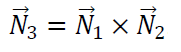
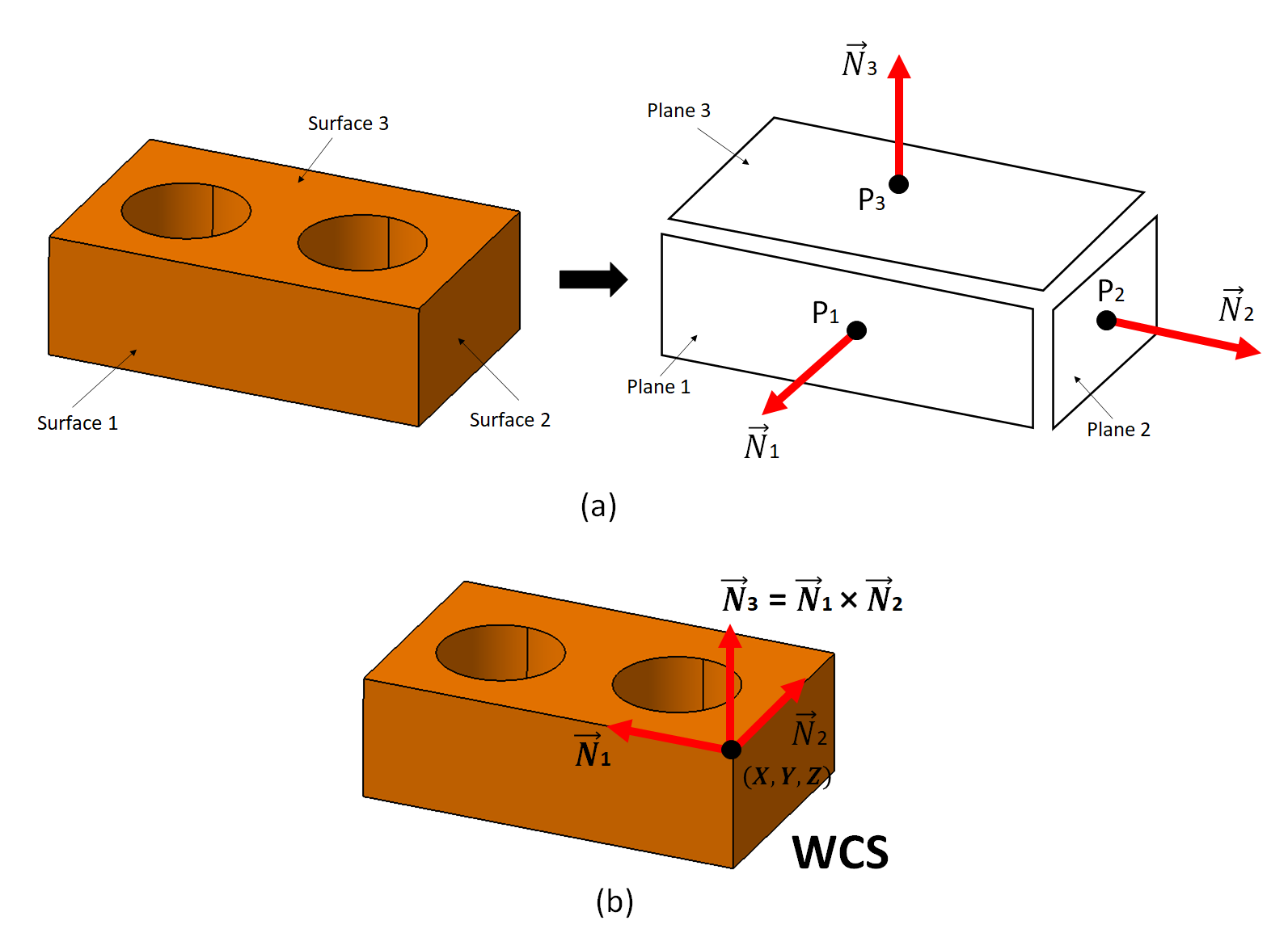
Figure 2 below shows the process of establishing a WCS from a part-alignment process for CMM measurement. In figure 2, a block workpiece is shown that is a common case in CMM measurement as well as for reference to explain how a part-alignment process is performed.
To determine the $X,Y,Z-$ coordinates for the centre location of the WCS, the centre location commonly can be:
- The intersection between three planes (the most common)
- The centre point of a circle
- The centre point of a sphere
- The intersection between two axes
- The intersections between an axis with a plane
To determine the unit vector 1 $(N_{1})$ and unit vector 2 $(N_{2})$ for the orientation of the WCS, these two vectors commonly can be (or the combination of):
- The normal vector of two planes
- The direction vector of a cylinder
- The direction vector of the edge of a block
Figure 2 above shows how to determine a WCS from the intersection of three planes and the normal vector of the two planes out of the three planes. This method to determine a WCS is the most common method to use.
In figure 2 above, the WCS will be placed on one of the top corners of the block. To realise this WCS, points on surface or plane 1, 2 and 3 are taken or probed. The number of points to be taken on each plane should be minimum to be three points.
As the rule of thumb, minimum four points need to be probed for a plane so that the averaging effect during a least-square fitting can be obtained. The least-square fitting is the process to associate a plane geometry to the probed or taken points of the planes.
The results of the fitting process on the probed points are a point on the planes and a unit vector that has an origin on the point on the plane (see figure 2a-right above).
Hence, when the point and the unit normal vector (originated from the point) on each plane has been determined, then, the WCS can be determined by calculating the intersection point from the three planes (fitted planes) as shown in figure 2b above.
This intersection point represents the location of the workpiece with respect to the MCS of the CMM in use.
Then, two normal vectors from two planes out the three planes are used as the unit direction vector of the WCS centred on the intersection point. The third unit direction vector can be obtained from a mathematical calculation, that is the results of cross-product between the two unit direction vectors.
READ MORE: The probing system of tactile-CMM: Important aspects to consider for probing system.

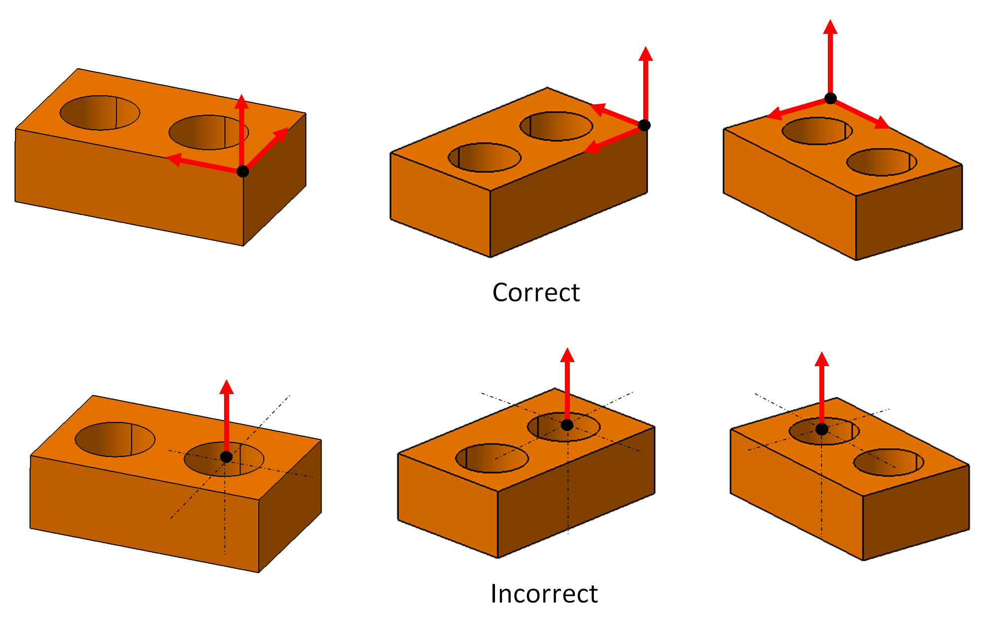
How to correctly determine work-piece coordinate system (WCS)?
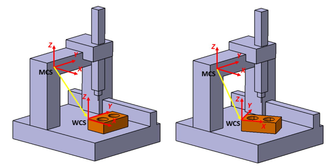
Examples of correct and incorrect WCS determination are shown in figure 3 below by using a block workpiece or part.
A correct WCS determination is when all 5 (+1) elements of the WCS, that are the WCS centre point $X,Y,Z-$ coordinates and the three unit normal vector $( N_{1}, N_{2}, N_{3} = N_{1} \times N_{2} )$, have been fully defined.
In figure 3-top row, it can be observed that all elements of the WCS have been correctly defined. The definition of “correctly defined” is by evaluating the change of position and orientation of the part.
When the part position and orientation are changed, the WCS can represent these changes. That is, the WCS position and orientation are also changed following the part movement and rotation.
However, in figure 3 bottom-row for incorrect WCS determination, when the WCS is not correctly defined, that is when all the 5 (+1) elements of the WCS are not fully defined, when the position and orientation of the part change or move, the WCS cannot represent that change. That is, the WCS will look the same even though the part position and orientation change as shown in figure 3-bottom row.
READ MORE: The probing system of tactile-CMM: The history, configuration and mechanism.
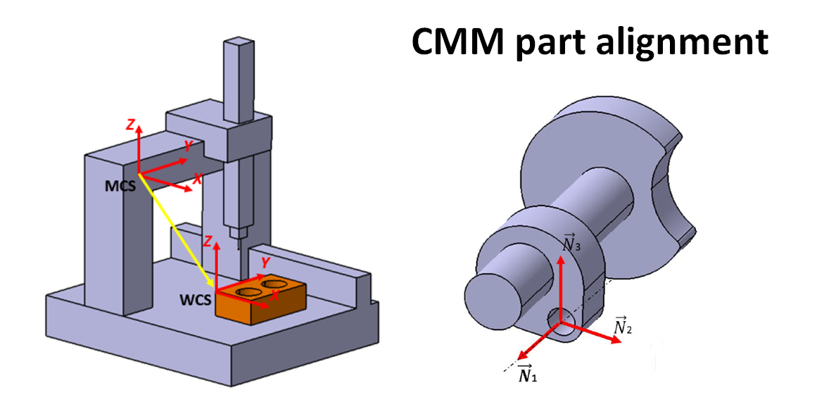
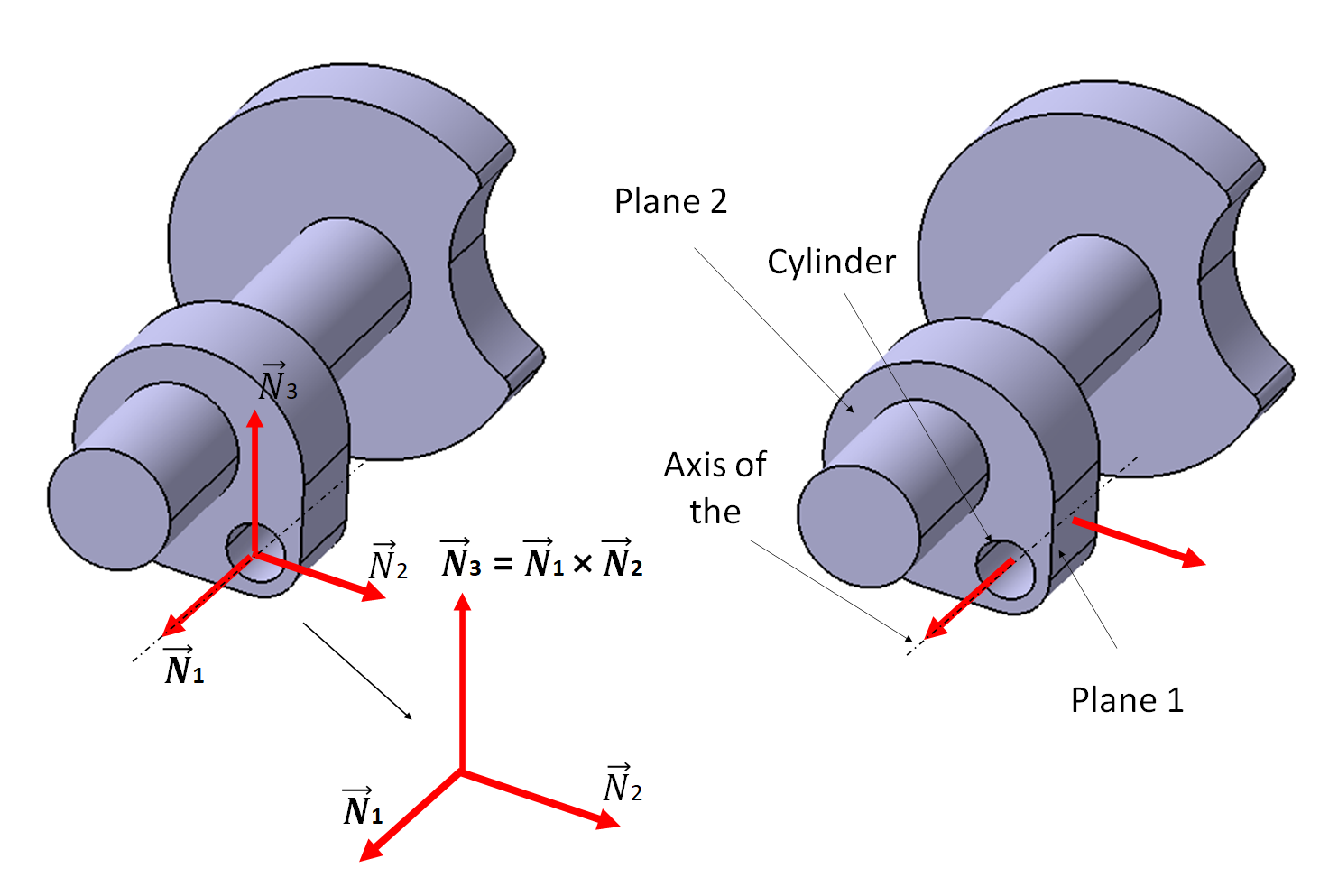
The determination of the work-piece coordinate system (WCS) of parts with complex shape
Figure 4 below shows a practical and real example on how to correctly determine a WCS and select required features on a part with complex shape or geometry.
In figure 4, since the part has a complex geometry, there are no three different planes with different unit normal vector directions to be selected in order to establish the WCS on the part.
Hence, for this complex part, the procedure to establish the centre location and unit vector directions of the WCS are as follow (following figure 4):
1. The centre point of the WCS (the $X,Y,Z-$ coordinates) is selected as the intersection point between the cylinder axis and plane 2 (see figure 4 below). Hence, the plane 2 and cylinder have to be probed to collect points to numerically reconstruct or fit the plane 2 and cylinder geometry.
2. The two unit normal vectors are determined as the unit directional vector of the cylinder axis (see figure 4) and the normal vector of the plane 1 shown in figure 4.
3. The third unit normal vector is determined as the cross-product form the two unit normal vectors that have been defined before, that is $N_{3} = N_{1} \times N_{2}$.
From the procedure above, all required elements or features to correctly establish the WCS can be obtained.
Conclusion
Part-alignment process on CMM measurement is instrumental. Because this alignment process is needed so that a CMM can locate or “see” the position and orientation of a measured part placed on the CMM’s measurement table.
Beside to know where the part on the CMM is, the part-alignment process also removes error sources originated from placement and fixturing-related errors. The reduction of these errors will improve the accuracy of CMM measurements.
The main goal of the part-alignment process is to establish a WCS on the measured part.
In this post, the procedure to determine a correct WCS is presented in detail. In addition, real practical examples on parts with simple and complex geometry are presented so that readers can have a practical understanding about part-alignment process on CMM.
You may find some interesting items by shopping here.