Geometric dimensioning and tolerancing: Datum feature simulator
In this post, we will discuss about datum feature simulator.

In this post, we will discuss about datum feature simulator.
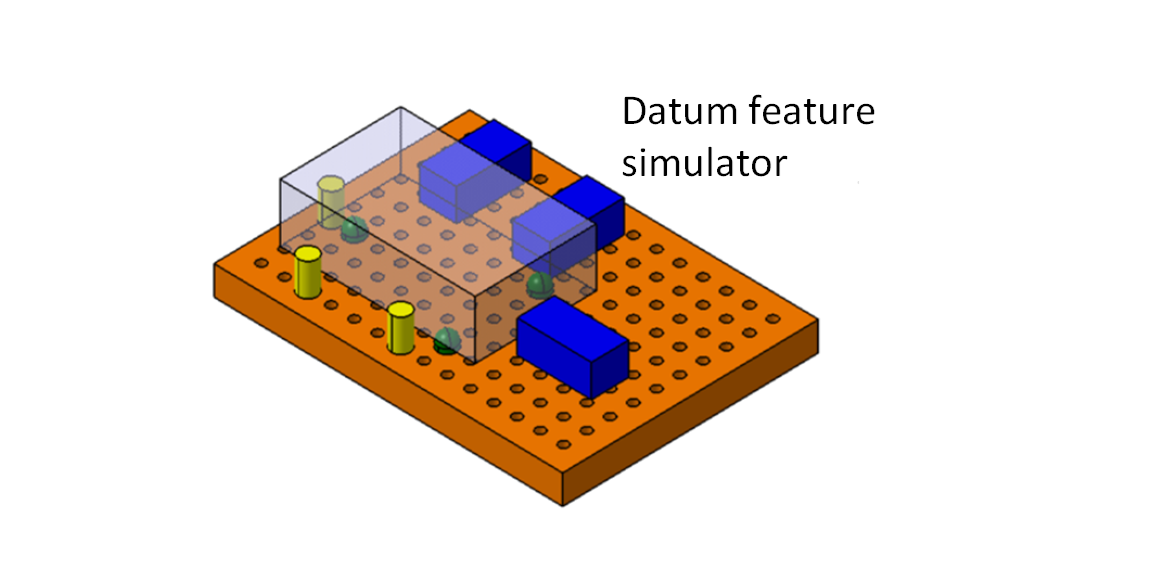
Datum feature simulator is the practical representation of the datum feature of a part in a real inspection (or manufacturing) process setup [1].
By the end of this post, we will understand about the theoretical datum feature and real datum feature simulator, the use of fixturing and gaging system to simulate datum features, the representation of datum feature at virtual boundary and the design, dimensioning as well as tolerancing a functional gaging system.
Let’s go into the discussion!
READ MORE: Tolerancing approach in geometric dimensioning and tolerancing
This mini plier combination set is the perfect everyday carrier that can fit in a small space. They can be used to fix most of daily assembly/disassembly problems
Definition of datum feature simulator
In short, datum feature simulator is a physical representation of a datum feature in a manufacturing or inspection process.
Hence only datum surfaces require datum feature simulator.
Example of datum feature simulators including
- Table of a machine or inspection instrument such as coordinate measuring machine (CMM),
- The collect chuck of a spindle in a turning or lathe machine,
- Functional gages representing datum feature in go-no-go inspection,
- Surface plates and locator in a fixturing system and others.
These examples of datum feature simulators are common components in fixturing and gaging system in manufacturing and inspection processes.
Note that all these physical surfaces as datum feature simulators are by themselves are not perfect. They also have geometrical imperfections.
Remember, all real surfaces have imperfections no matter how small their tolerance is.
That is why, datum feature simulator should have high tolerance to be much higher than the tolerance of the datum features they represents.
This is so that the datum feature simulator will minimise geometrical error propagation on the whole parts and their assembly [3][4].
Imaginary datum feature simulator
Imaginary dam feature simulator is an imaginary perfect geometry or surface of a datum feature simulator including a perfect planar surface, a perfect cylinder and other perfect geometry shapes.
These perfect geometry is the perfect geometry shapes of the counterpart of a datum surface.
The important thing to note is that imaginary datum feature simulator is a theoretically perfect boundary representation.
That is, imaginary datum feature simulator is the virtual condition (actual mating envelope) of a future it represents.
In summary, datum feature simulator usually represents the virtual condition of the counterpart it represents and is usually interchangeable with or referred to imaginary datum feature simulator.
Remember thought, in reality a physical datum feature (datum feature simulator) should have tighter tolerance than the datum feature it represents.
READ MORE: Understanding fixturing constraints: locator, clamping, support and guide
Practical example of datum feature simulator
Planar datum feature simulator
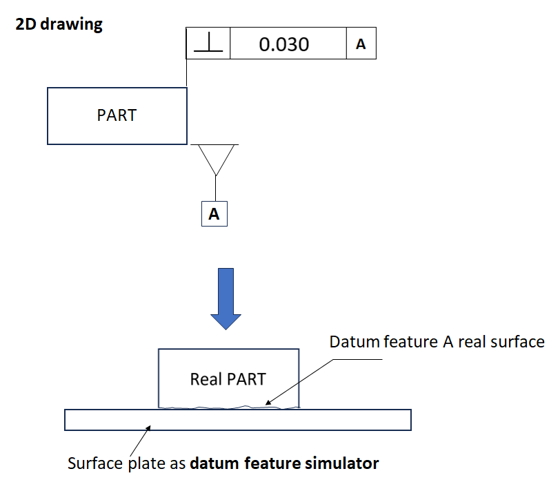
For a planar surface, such as primary datum on a part, the (imaginary) datum feature simulator is a plane derived from the contact of minimum three highest points on the datum feature.
In reality, the datum feature simulator typically represented by a planar surface (surface plate) touching the datum surface in a fixturing system.
Figure 1 shows the example of the datum feature simulator on a primary datum feature on a part.
Cylindrical datum feature simulator
For cylindrical surfaces, typically many, if not all, of the datum features are cylindrical surfaces.
Typically, on a cylindrical part, the primary datum feature is the surface of the largest cylinder.
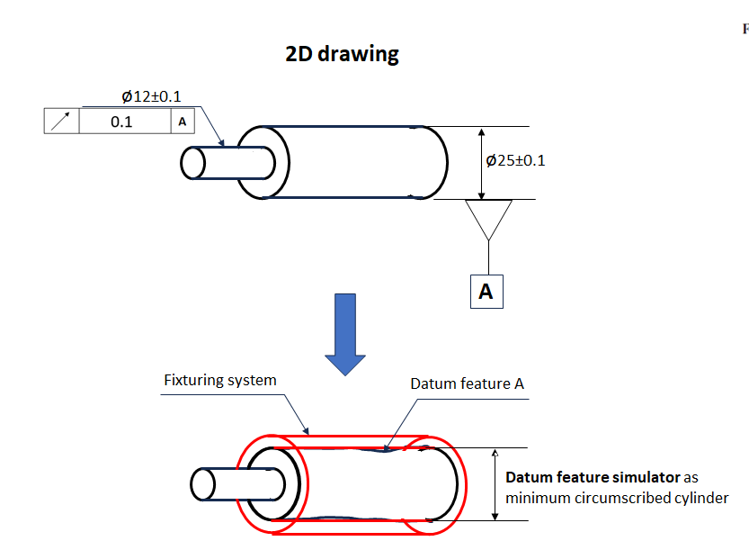
The (imaginary) datum feature simulator is then a cylinder that can fit the whole surface of the cylinder representing the primary datum surface.
The datum feature simulator is a minimum circumscribed cylinder with respect to the cylinder with the primary datum surface.
Figure 2 below shows the datum feature simulator of a cylindrical datum surface. The simulator is a minimum circumscribe cylinder of the cylinder of the primary datum surface.
Datum feature simulator for orientation tolerance
Another unique case is the datum feature simulator for orientation tolerance.
As orientation error is a related tolerance, hence orientation tolerance should be not a primary datum.
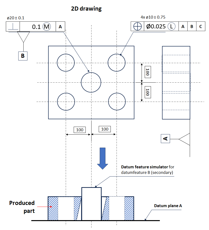
In this case, we want to construct the (imaginary) datum feature simulator for orientation tolerance as secondary datum.
The datum feature simulator typically will be a pin representing the actual tolerancing error.
Figure 3 below shows an example of pin as datum feature simulator for orientation tolerance datum surface/feature.
Datum feature simulator for MMC condition (as a functional gage)
This example is in the case of a GO – NO GO gaging system. Gaging system is a functional gage to check a geometrical feature either within or outside its tolerance.
In gaging system, the gage itself acts as the datum feature simulator for inspected parts with the gage.
Figure 4 below shows the example of a part with two holes features and three datums: A (primary), B (secondary) and C (tertiary).
This part has two location tolerance for the two holes. The function of the holes is to mate with their counter pins.
The datum feature A is the top surface of the part. Meanwhile, the datum feature B and C are the long side and short side surface of the part respectively.
Datum feature A (since it is the primary datum) has an unrelated flatness tolerance of 0.1mm. Datum A has the tightest tolerances since this is the primary datum.
Meanwhile, datum feature B has perpendicularity tolerance of 0.2mm with respect to datum A and datum feature C has perpendicularity tolerance of 0.3mm with respect to datum A and B.
The holes have nominal diameter of 15mm with size tolerance of 0mm-0.02mm. The geometrical tolerance for the holes is position tolerance of 0.2mm with MMC modifiers with respect of Datum A, B and C.
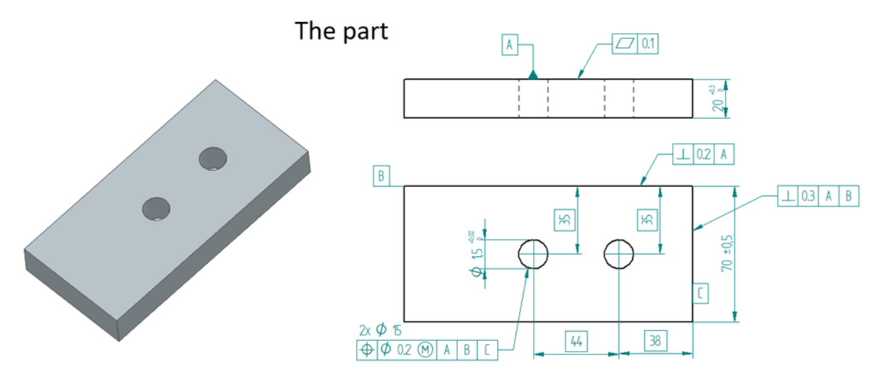
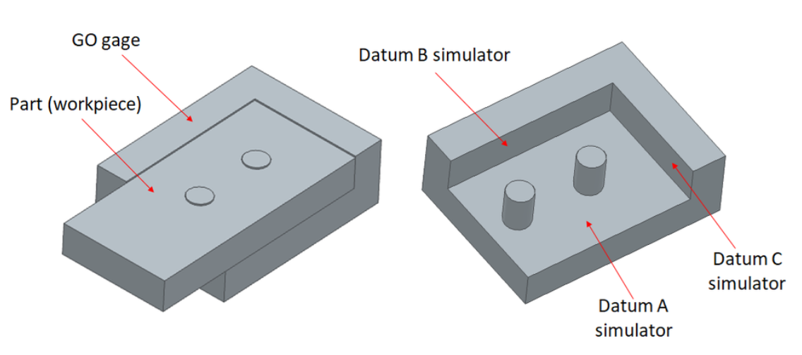
Figure 5 below shows the datum simulator as the gaging system (GO gage) to verify the geometrical tolerances of the part (figure 4 above).
From figure 5, the GO gage has two pins gage to verify the hole position tolerances as well as datum feature simulator to locate the part when we perform the gaging (inspection) process.
Note that the geometrical tolerance of the gage features, such as datum simulator and the pin are 10% of the tolerance of the par.
Any geometrical deviation and deformation of the GO gage will increase probability to reject good parts and accept bad parts!
This requires that the GO gage must be much more accurate than the part to check to make the inspection process meaningful.
In addition to high accuracy, the material of the GO gage should have higher thermal stability than the material of the part to make sure there is no long-term deformation of the GO gage.
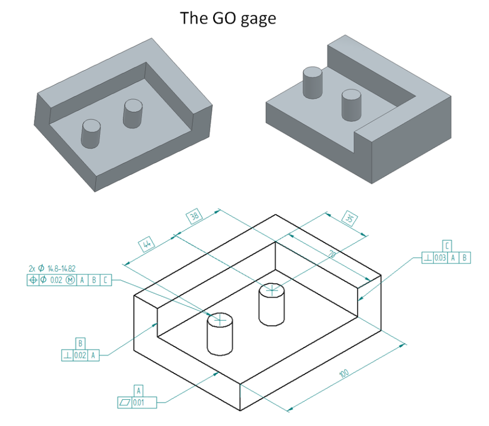
Figure 6 below shows how the gaging system (the datum feature simulator) fit the part to be inspected.
The explanation of the datum feature simulator (the gaging operation) is as follows.
The datum feature simulators for datum A, B and C are used to locate the part and satisfy the datum requirements (by simulating the part datum feature A, B and C) of the position tolerance of the part.
The advantage of this GO gaging system over a traditional coordinate measuring machine is we can quickly check the hole tolerance of the part.
Hene this method is suitable for the inspection of mass-produced parts.
READ MORE: Geometric dimensioning and tolerancing: Datum target
Conclusion
In this post, we have discussed the basic definition of datum feature simulator.
Datum feature simulator is a physical representation of a datum feature in a manufacturing or inspection process.
There are various types of datum feature simulator following the various types of datum feature surface and tolerance types, including primary planar datum, primary cylindrical datum, secondary orientation datum and a gaging system as datum feature simulator.
Of course, there will be more types of datum feature simulator in a manufacturing or inspection process setup.
Reference
[1] ASME Y14.5-2009, Dimensioning and Tolerancing: Engineering Drawing and Related Documentation Practices.
[2] Meadows, J.D., 2017. Geometric Dimensioning and Tolerancing: Applications and Techniques for Use in Design: Manufacturing, and Inspection. Routledge.
[3] Fischer, B.R., 2004. Mechanical tolerance stack-up and analysis. CRC Press.
[4] Whitney, D.E., 2004. Mechanical assemblies: their design, manufacture, and role in product development. New York: Oxford University press.
If you want to support me developing this blog, you can support me here.
This Were screwdriver set is good for everyday carrier and can help finishing many assembly/disassembly jobs.