Geometric dimensioning and tolerancing: Datum target
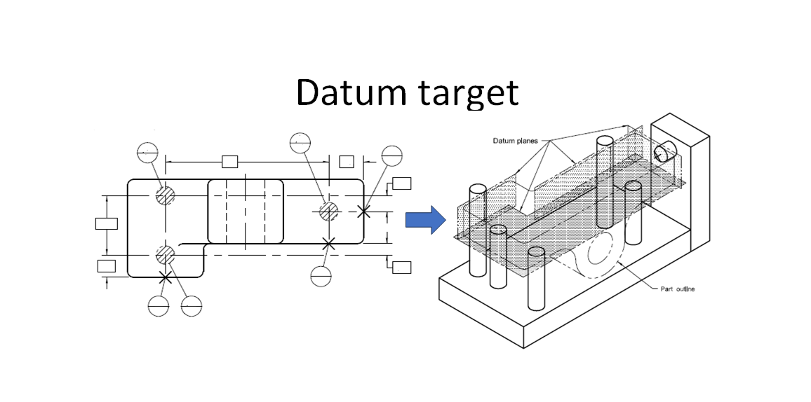
This post will discuss datum target, how to specify datum target and how to stabilise or fixture complex and/or flexible parts (such as sheet metal, warped or welded part, rough casting/moulded and forging) with datum target.

This post will discuss datum target, how to specify datum target and how to stabilise or fixture complex and/or flexible parts (such as sheet metal, warped or welded part, rough casting/moulded and forging) with datum target.
Datum targets can be points, lines or areas on a surface [1].
We typically use this type of datum for flexible parts such as sheet metal and plastics with free-form or curved surfaces in addition to stabilise inherently unstable parts including casted or forged parts.
One important note is datum target should only be used to establish datum planes or axes and hence to construct datum reference frame (DRF).
This DRF is the reference, in feature control frames, for other geometric tolerancing of features on a part.
That is, if a datum target is not used to construct a DRF, hence we should not put this datum on our 2D drawing.
READ MORE: Geometric dimensioning and tolerancing: Datum selection
This Knipex mini plier combination set is the perfect everyday carrier that can fit in a small space. they can be used to fix most of daily assembly/disassembly problems.

Datum target symbol and assignment
There are three types of datum target symbol: point contact, line contact and area contact.
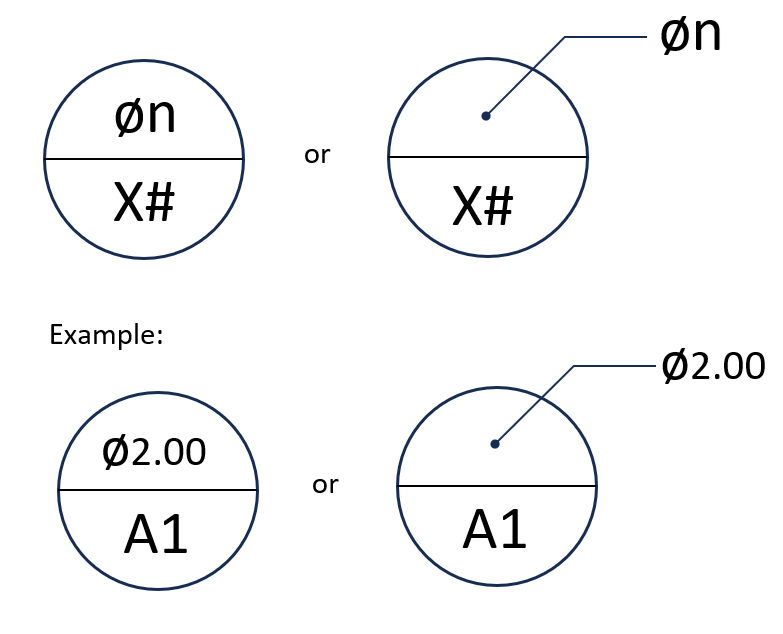
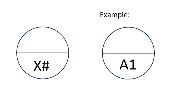
The general symbols of datum target for area contact, and point and line contact are shown respectively in figure 1 and figure 2 below.
In figure 1, for area contact datum target, the symbol contains not only datum name and number “X#”, but also contain the diameter of the area “øn”.
Also, the diameter of the area can be written inside the circle symbol or outside the circle with a pointing line.
In figure 2, for both point and line contact, the symbol only contains datum name and number “X#”.
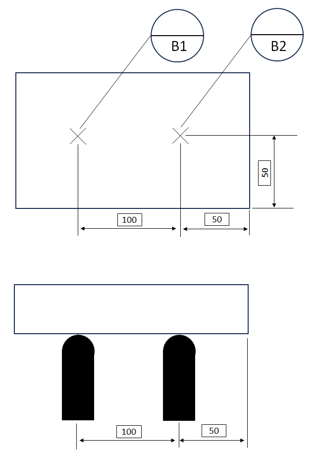
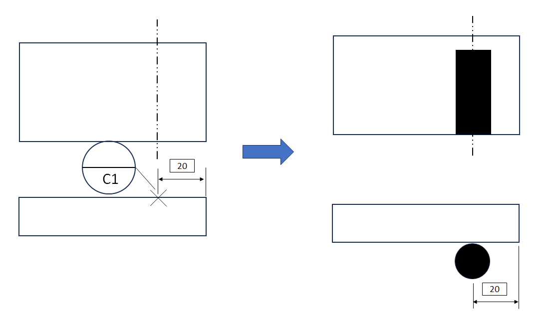
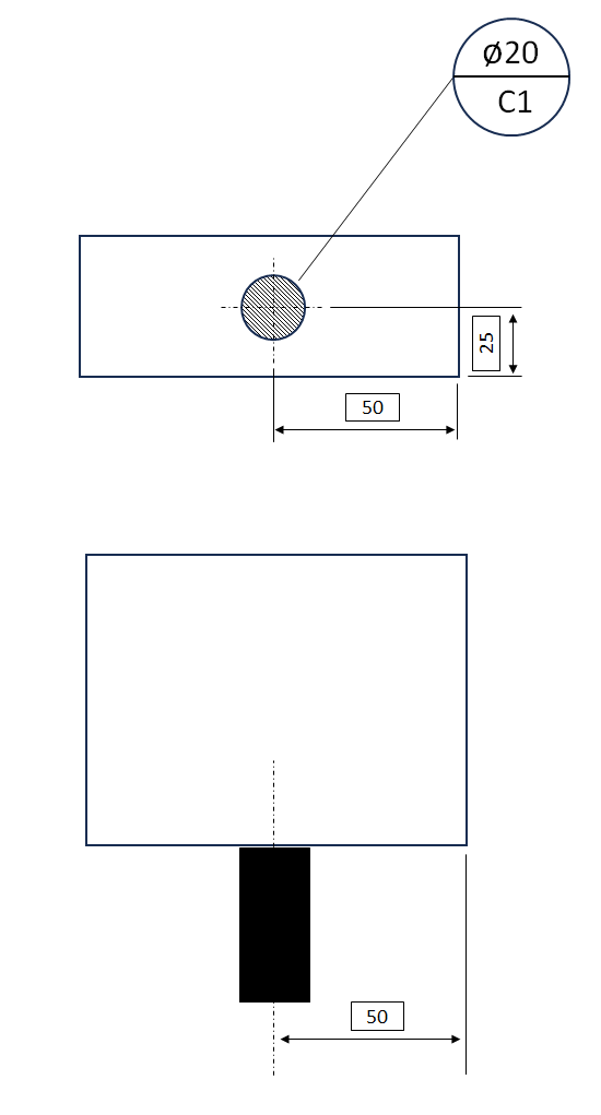
Some practical examples of the use of datum target (for point, line and area contact) on 2D technical drawing and their implementations on assembly or inspection or manufacturing process are shown in figure 3, figure 4 and figure 5 for point, line and area contact, respectively.
Figure 3 below presents the example of datum target for point contact. In the technical drawing, only ‘X’ symbol is signed with a given datum name (without the datum size). The realisation or implementation of this datum is that the datum target area will have point contact with a pin with a spherical tip or the pointed tip of a cone as the datum target simulator.
Figure 4 below shows the example of datum target for line contact. We use ‘line’ symbol to represent a datum target for line contact with a given datum name (without the datum size). To establish this line contact datum target, we contact the datum surface with the side of cylindrical pint as the datum target simulator.
Figure 5 below illustrates the example of datum target for area contact. For area contact, we use ‘a filled circle’ symbol to represent the contact area of the datum with its simulator. For this datum target, the datum sign has both datum name and area diameter. We implement this datum by contacting the datum target area with the flat side of a cylindrical pin as the datum target simulator.
READ MORE: Geometric dimensioning and tolerancing: Wall-thickness analysis and LMC modifiers
Some examples of datum target applications
We will discuss several practical and common examples of datum target implementations. Typically, datum target simulators are locators on fixturing systems for repeatable part placement and orientation.
Here in the example, datum target can also applied to prismatic parts without curved surfaces.
The locators can be a pointed-tip cone and spherical-end pin for point contact simulator, cylindrical pin for line contact simulator and flat-head or squared pin for area contact simulator.
These locators typically have position or location dimensioning and tolerancing. The best practice for the location tolerance and dimension for these locators follow the established dimensioning and location tolerance in our companies.
However. Although not the best practice (not recommended), the plus or minus tolerancing and dimensioning are still allowable.
Typical example for point and line contact datum target
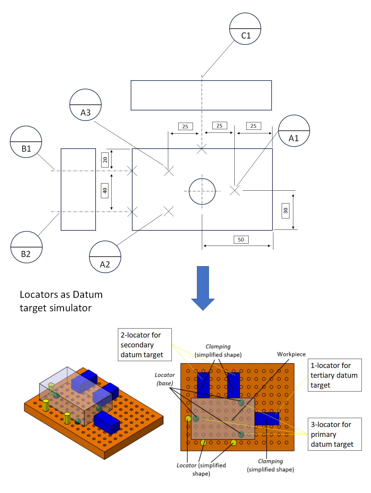
Figure 6 below shows a common example of point contact datum target. In this example, the datum target is applied to a prismatic part such that the datum target simulators from kinematic constraints 3-2-1 system.
Spherical pins are used to simulate the point-contact datum target (figure 6 bottom). In practice, these datum targets are tolerance using location tolerancing following the gage applied in our companies.
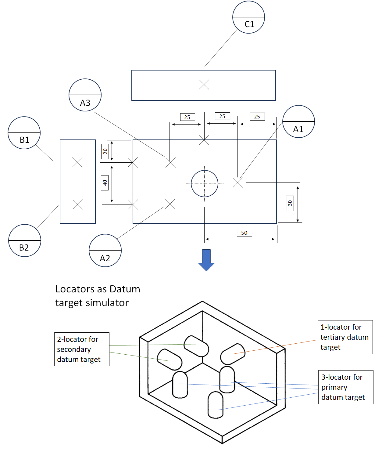
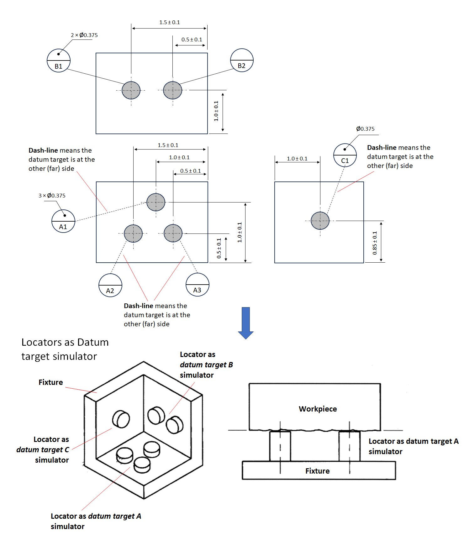
Figure 7 below shows a common example of datum target line contact combined with point contact. In this example, the primary datum are point-contact datum targets. Meanwhile, the secondary and tertiary datum target are line contact.
These point and line-contact datum targets form the kinematic 3-2-1 constraints for the part (shown in figure 7 bottom).
Typical example of area contact datum target
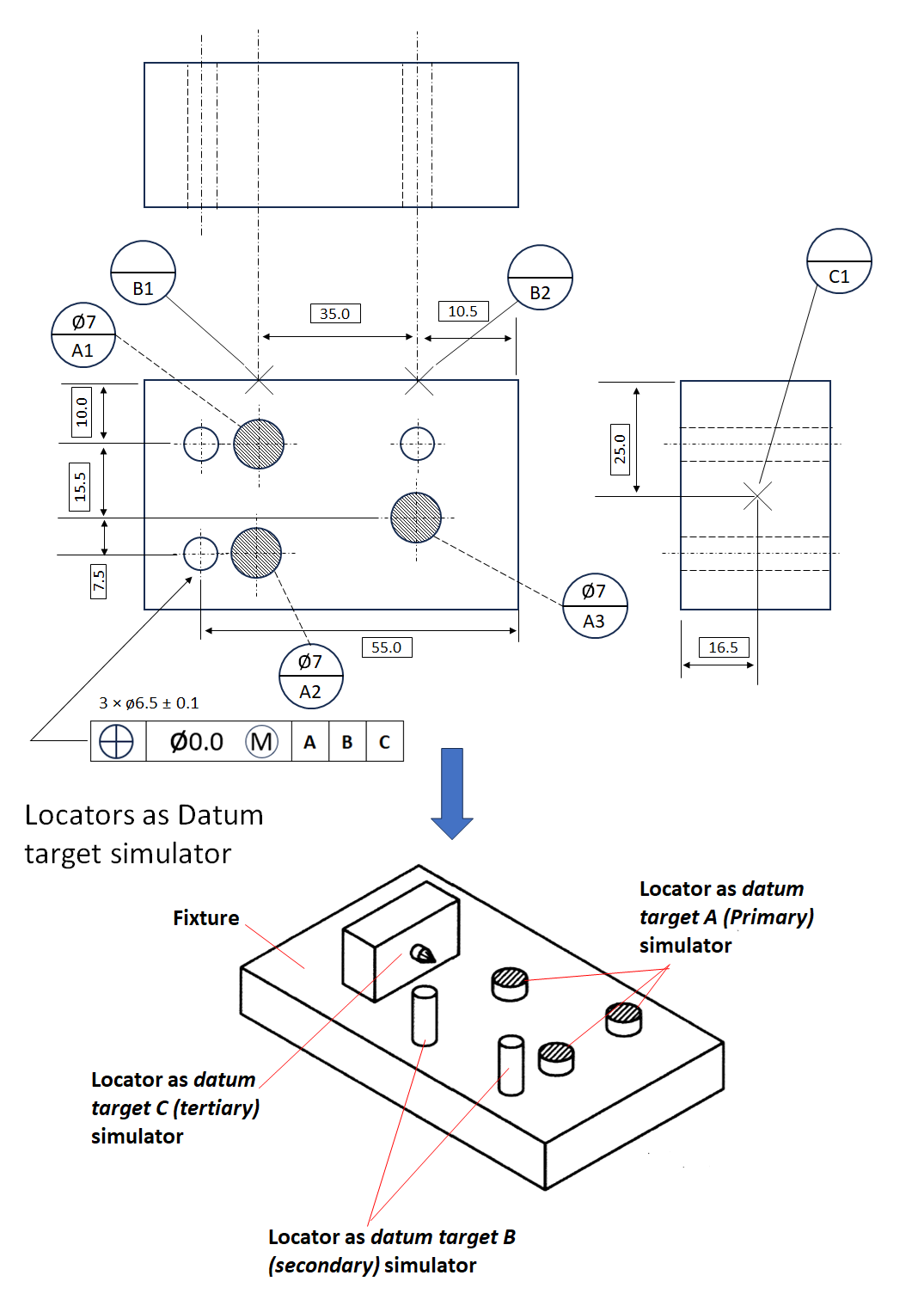
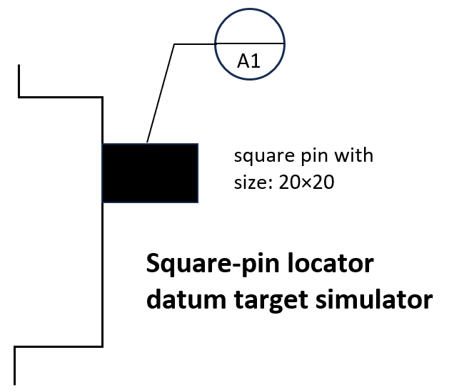
For area contact datum target, a line-patterned filled cylinder (or square) can be used as shown in figure 8 below. The circle diameter of the datum target symbols represents the area of contact of the flat-head of cylinders, representing the datum target simulator.
In this example, all primary, secondary and tertiary datum use area-contact datum target and form the kinematic 3-2-1 constraints.
Typical example of combination of area, line and point contact datum target
In practice, very often we will find datum target combinations of point, line and area contact. This combination provides the best datums for complex parts such as sheet metal parts.
Figure 9 below shows the typical example of datum target combinations. In this figure, the primary datum uses three circle area contact datum target with flat-head cylinders as datum simulators.
The secondary datum uses line contact datum target simulated by the side of cylindrical pin.
And finally, the tertiary datum uses a single point contact simulated by a pointed-tip cone locator.
In figure 9, only the locators are shown without any clamping components.
All of these datum target combinations form the kinematic 3-2-1 constraints to minimise, if not eliminated, residual stress on precisely locating the part on its fixturing system.
READ MORE: How BMW reduces their assembly cost by optimising assembly features and fixturing constraints
Example of datum target on sheet-metal part
Perhaps, the most useful application of datum target is in automatic body assembly applications.
Automotive body is constructed from multiple pieces of sheet-metal part with complex shape, thickness and may have some degrees of flexibility (deformed shaped) [3][4].
This type of parts makes datum target feature in GD&T becomes very important and needed.
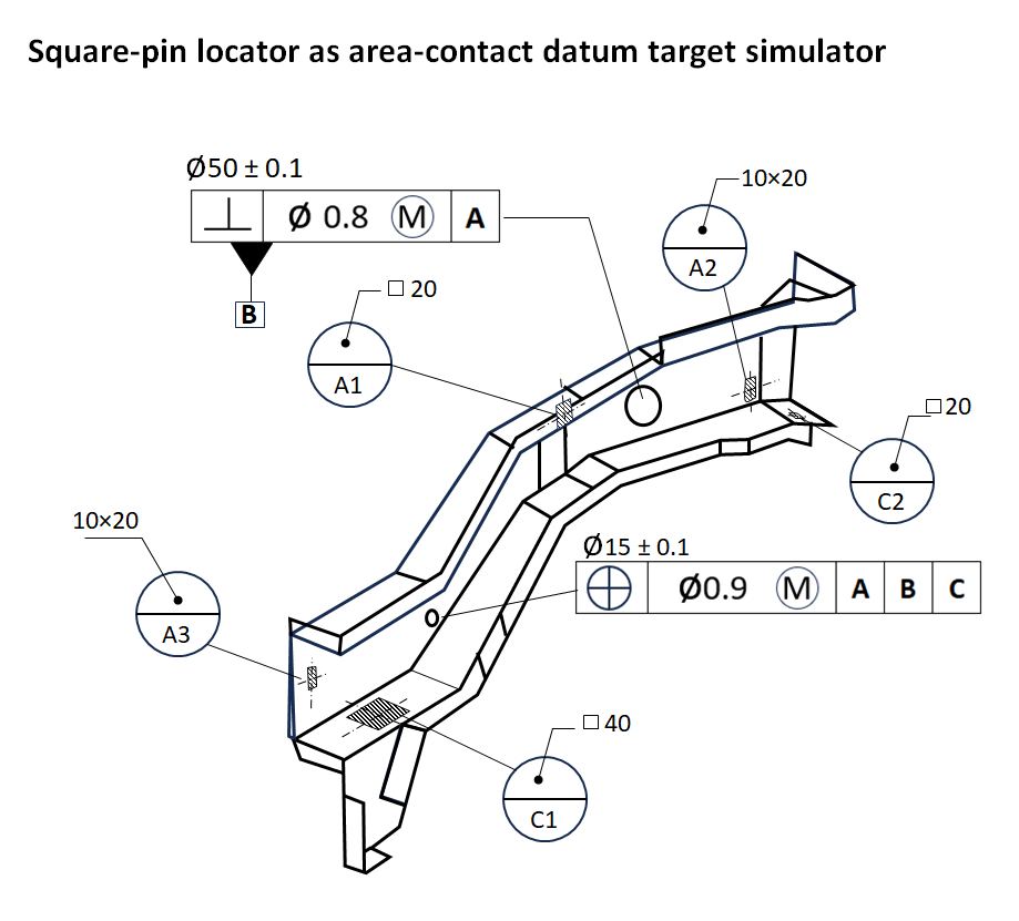
Figure 10 below shows an example of sheet-metal part of pilar in an automotive body construction. In this figure, the three primary and two secondary datum targets are squared area contact while single tertiary datum target uses a standard hole datum feature.
From all of these datum combination, the kinematic 3-2-1 constraints can be achieved. Typically, this fixturing system (containing locator and clamping) is used during a spot-welding process.
Figure 11 below shows the example of datum target simulator applications for squared area contact. In this figure, protruding squared pins touch the datum target area contact as per the 2D drawing to simulate the datum target and to constraint the part for repeatable part placement on its fixturing system.
Remember that in the real application, the position of the area contact on the parts follow the gauge of the fixturing system of the part.
READ MORE: 3D tolerance stack-up analysis with examples
Conclusion
In this post, we discuss the definition, function as well as symbol of datum target. This type of datum is not only applied for complex or flexible parts with curved surfaces (such as sheet metal parts), but also on prismatic parts.
Typically, datum target simulators are in the form of locators. These locators can be pointed-tip cone or spherical-end pins for point contact simulator, cylindrical pin for line contact simulator and flat-head cylinder or squared pins for area contact simulator.
Several practical examples have been given, covering prismatic and sheet-metal parts, with different types of datum target types (point, line and area contact) and symbol implementations.
Reference
[1] ASME Y14.5-2009, Dimensioning and Tolerancing: Engineering Drawing and Related Documentation Practices.
[2] Meadows, J.D., 2017. Geometric Dimensioning and Tolerancing: Applications and Techniques for Use in Design: Manufacturing, and Inspection. Routledge.
[3] Fischer, B.R., 2004. Mechanical tolerance stackup and analysis. CRC Press.
[4] Whitney, D.E., 2004. Mechanical assemblies: their design, manufacture, and role in product development. New York: Oxford university press.
If you want to support me developing this blog, you can support me here.
This Were screwdriver set is good for everyday carrier and can help finishing many assembly/disassembly jobs.