Tolerancing approach in geometric dimensioning and tolerancing
In this post, we will focus on the basics of datum and tolerance selection.


Geometric dimensioning and tolerancing (GD&T) is a design language encoded into symbols.
This language is made by a design engineer for their manufacturing and inspection engineer team members.
In this post, we will focus on the basics of datum and tolerance selection.
The basics include:
- Important notes on datum feature symbol placement.
- Datum feature selection.
- Practical steps in determining datum feature and their geometric tolerances.
Remember, since GD&T is a language, any geometric control and tolerances can be and should be read as a sentence to understand why those geometric tolerance symbols are used in 2D technical drawings.
READ MORE: Geometric dimensioning and tolerancing: Datum target
This mini plier combination set is the perfect everyday carrier that can fit in a small space. They can be used to fix most of daily assembly/disassembly problems

Important note on Datum feature symbol placement!
Here, we will discuss briefly the important details for datum feature symbol placement in a technical drawing [1].
There are several ways of putting or placing datum symbols on technical drawings, including:
- On the surface outlines, either planar or spherical surfaces.
- Other than on surface outlines, such as feature control frame, dimension line, extension line, chain line and phantom line.
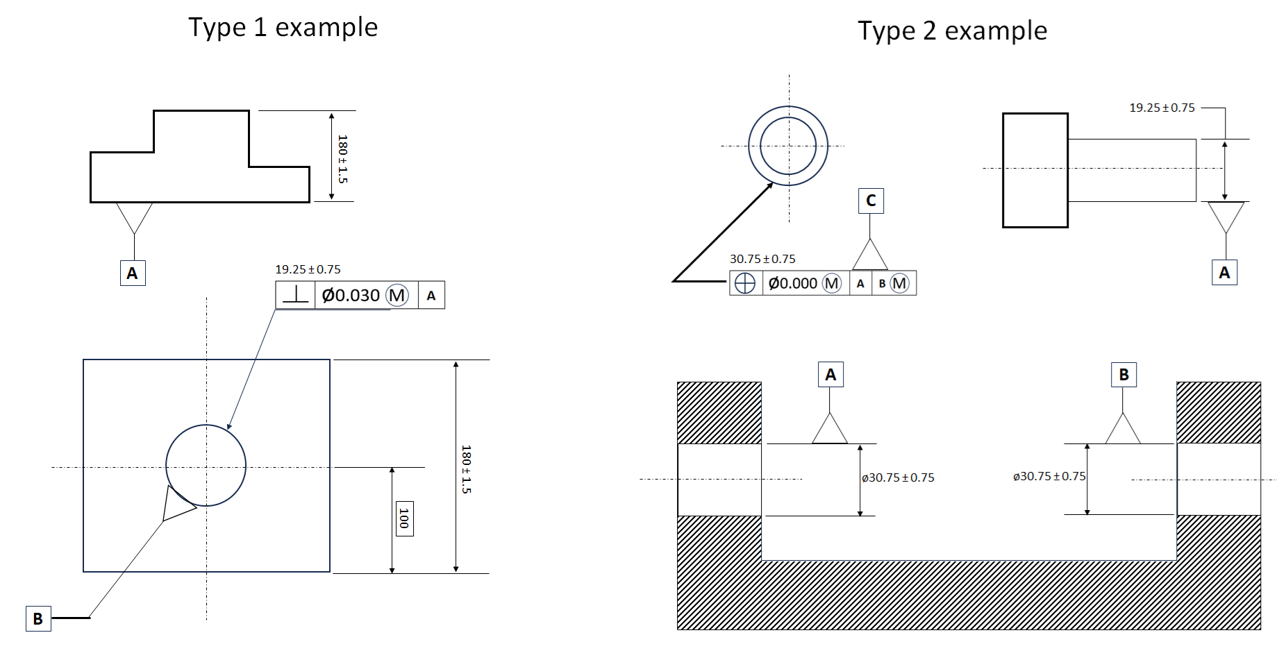
Hence, there are two types of datum based on datum symbol placements:
- Type 1: Datum as datum feature only.
This type 1 datum is represented by datum symbol placed on surface outlines. That is, the datum symbol is placed separated from dimension line, feature control frame, extension line and phantom line.
- Type 2: Datum as datum feature of size.
This type 2 datum is represented by datum symbol placed on other than surface outlines. This means that the datum feature will be either a centre line, centre plane, datum axis or datum point. This type of datum symbol placement is the most common case.
For irregular or free-form surfaces, for example on sheet-metal parts, the symbol of a datum feature could be placed on axes or planes established by datum targets.
In addition, datum feature symbol can be placed on feature control plane (top or below).
Figure 1 below shows some examples of datum symbol placement for datum type 1 and datum type 2. This difference seems small, but it is significant in in GD&T as it will affects all the manufacturing and inspection processes on how we place or position parts.
The selection of datum and datum feature
Important details for datum feature symbol are as follows:
- Datum features are real surfaces of a part used to establish an imaginary plane or axis to measure or verify related geometrical tolerances, such as orientation, location and run-out tolerances.
- Datum features are selected from surfaces on a part that serve a function, such as surface to seat or mate or align to another part in an assembly.
For Primary datum, the selected surface should be sufficiently large to stabilise a part in an assembly, manufacturing and inspection processes, including surface as angle alignment reference for the part to fit its mating plate in an assembly, surface where the part will be bolted to another mating part and/or surface that make a large area of contact to its mating part.
For Primary datum, the geometric tolerance should be unrelated as it is the first datum and has the strickest tolerance value to ensure repeatability and reduce error propagations on an assembly [2]. For this reason, form tolerances should be used for primary datum.
Primary datum typically uses flatness and cylindricity tolerances.
- Datum reference frame is a coordinate system on a part that is constructed from the intersection of three perpendicular planes or between plane and axis and is as reference for verifying geometric tolerances, to stabilise the part and to set up a measurement from [3][4].
We must remember that when selecting datum features and assign tolerances to them, we should consider additional aspects such as the efficiency in manufacturing and inspection processes for the datum features.
READ MORE: 3D tolerance stack-up analysis with examples
Steps in determining datum features and their geometric tolerances
Example 1:
This example uses 2D technical drawing as presented in figure 2 below.
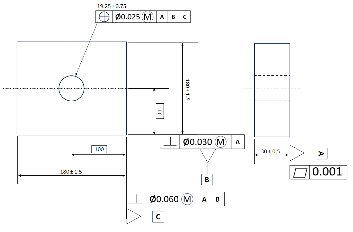
Based on figure 2 above, we can approach the geometric tolerancing of the part as follows.
The primary datum A is obvious. The base surface with the largest surface area and where it mates or rest on another mating part is selected. Form tolerance, in this case flatness, is given. Since this is the first datum on the part, no relation is given.
Datum A will have a contact to another surface at minimum three-point contact.
The secondary datum B is a surface used as reference of the hole measurement from. There are two options, either the right side or the bottom side (from the front view of figure 2 above).
In this case, since the surface length is the same between the right and bottom side, we can select the right surface as datum B.
Datum B is given perpendicularity tolerance with respect to datum A with relaxed tolerance value with respect to datum A. There is a common rule that datum B should be toleranced 3x higher than datum A to avoid datum A excessively rocking when inspecting datum B.
Datum B only refers to datum A as at this point, only datum A exists.
Datum B will have a contact to another surface at minimum two-point contact.
The tertiary datum C is the remaining bottom side with perpendicularity tolerance higher than datum B tolerance, similarly can be 2-3x higher than datum B. This datum C will have reference to datum B and datum A.
Datum C will have a contact to another surface at minimum one-point contact.
These three datums: datum A (primary), B 9secondary) and C (tertiary) will establish the datum reference frame for the part.
Finally, the hole feature is positioned with respect to the three datums. The hole is a mating feature to a counter-part shaft or pin (external feature of size).
Position tolerance is applied to control the hole position with respect to the three datums with significantly larger tolerance than the tolerance of the datums.
Since the function is just to make sure its mating pin or shaft can enter the hole, the larger the hole produced (within its size limits) the easier the pin/shaft can enter or mate the hole.
Hence, Maximum Material Condition (MMC) modifier is applied to the hole.
In addition, if the hole is made larger, there will be bonus tolerance on the position tolerance of the hole.
Example 2:
This example uses 2D technical drawing as presented in figure 3 below.
Note that the primary datum always has the strictest tolerance, the further the tolerance from the primary datum, such as secondary, tertiary and other non-datum features, the tolerance will get relaxed [3].
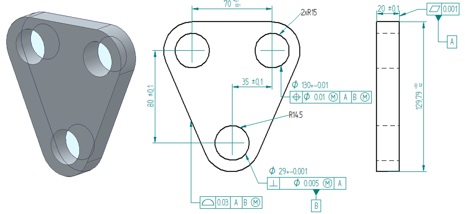
From this example, the Primary datum, Datum A, the planar surface as the base of the part is selected. Fatness tolerance is given for this planar surface. For the case of when the cylindrical surface is selected, cylindricity tolerances shall be used.
Remember that additional aspect to consider is to ease manufacturing and inspection processes, such as easy to access as well as tolerance value that follow the capability of manufacturing an inspection process accuracy.
Secondary datum, datum B, for this example selects the single hole future on the part (figure 2) and shall be toleranced with respect to datum A. The secondary datum B is perpendicularly constraint to datum A.
This secondary datum, datum B, is selected such that it contributes to establish the origin of measurement to align the part to its mating part in an assembly.
This datum B has a tighter tolerance with respect to other holes since if a shaft can fit datum B, datum B gives better alignment for the other two holes.
In this example, two datums are enough to construct the datum reference frame from three intersections of planar surfaces.
The first planar surface is datum A and the other two planar surfaces are two surfaces intersect at the cylindrical axis of datum B and are perpendicular each other as well as to datum A.
Hence, the reference point of the part is the point derived from the intersection of cylinder axis of datum B and the planar surface of datum A.
READ MORE: Understanding fixturing constraints: locator, clamping, support and guide
Conclusion
In this post, we discuss approaches for geometric tolerance selections applied to part surfaces.
We first discussed the basics of datums symbol placement on a 2D technical drawing. Then, we discuss the basics of feature selections used as datums.
Finally, two practical examples of geometric tolerance approaches and selections are given. The concept can be expanded to any tolerancing tasks on complex parts.
Reference
[1] ASME Y14.5-2009, Dimensioning and Tolerancing: Engineering Drawing and Related Documentation Practices.
[2] Whitney, D.E., 2004. Mechanical assemblies: their design, manufacture, and role in product development. New York: Oxford University press.
[3] Meadows, J.D., 2017. Geometric Dimensioning and Tolerancing: Applications and Techniques for Use in Design: Manufacturing, and Inspection. Routledge.
[4] Fischer, B.R., 2004. Mechanical tolerance stack-up and analysis. CRC Press.
If you want to support me developing this blog, you can support me here.
This Were screwdriver set is good for everyday carrier and can help finishing many assembly/disassembly jobs.