Datum references, tolerance zone and material condition in GD&T
This post explains some fundamental elements of GD&T. The elements are datum reference (datum reference frame), tolerance zone and material condition.
This post explains some fundamental elements of GD&T. The elements are datum reference (datum reference frame), tolerance zone and material condition.
All GD&T tolerances are built on top of all these three elements. The understanding of these three elements is essential to thoroughly understand GD&T.
Tolerance zone maybe the most fundamental building block of GD&T. Because, all GD&T conformance and non-conformance decisions are based on verifying features with respect to one or more tolerance zones.
Datum reference provides the origin of coordinates of all GD&T tolerances on a part. All feature positions will be based on this datum reference.
Material condition is a condition to explain how a larger or smaller tolerance values can be obtained when a feature of interest is made smaller or bigger that its nominal size. This material condition concept can be a huge saving in the quality inspection process of parts.
Finally, real examples showing the benefits of using MMC and LMC symbols in feature of size are presented at the end of this post.
Let’s get into them one by one.
Datum and datum reference
Especially for GD&T tolerance with relations (for example orientation, location and run-out) that require datum, a datum system is necessary to be the reference point for all GD&T tolerance verification and comparison.
This datum system is commonly called datum A, B and C (sometimes until D or E depending on tolerance situations and requirements). These datums will intersect each other and the point of all the intersections is called datum reference (datum reference frame). This datum reference is the main reference for all GD&T tolerance on a part or component.
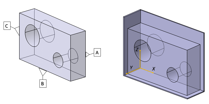
Figure 1 shows a datum system and datum reference/datum reference frame. In figure 1 left below, a datum system containing three datums: datum A, datum B and datum C is shown. A datum can be, for example, a surface or an axis from a symmetrical feature or other geometrical features.
Datum A is the main datum on GD&T tolerances on a part and also the main reference for the other datums (in this case datum B and datum C) on the part. In general, datum A commonly applied to the most stable feature on a part, such as the surface with the largest surface area or as the base of the part.
In figure 7 left above, datum A is applied to the back surface of the part because it has the largest surface area on the part. For datum A, since it is the main and first datum, only un-related GD&T tolerances applied as datum A, such as flatness, roundness and cylindricity.
In addition, the tolerance of datum A should be the tightest among the other datums (in this case datum B and datum C) since datum A is the reference and each small deviation on the manufacturing of datum A will propagate and amplified to the deviation to other features.
The reason datum A should have the tightest tolerance and manufacturing accuracy is because in any manufacturing processes, such as machining and inspection processes, such as by using CMM, the surface of datum A on the part should touch the main table of the machine tool or the CMM.
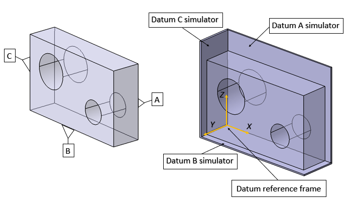
In figure 7 right, a datum reference frame is shown. Datum reference frame is a point as the result of the intersection of all the datum planes/features represented by datum simulators (see figure 7 right). Datum simulator is a surface that directly touch a datum surface and simulate the datum on a part.
Datum reference frame is the coordinate reference to verify the GD&T tolerances on a part for related tolerances. In real situation, a datum simulator can be the base table of a measuring instrument for datum A and the surface of fixturing for other datum.
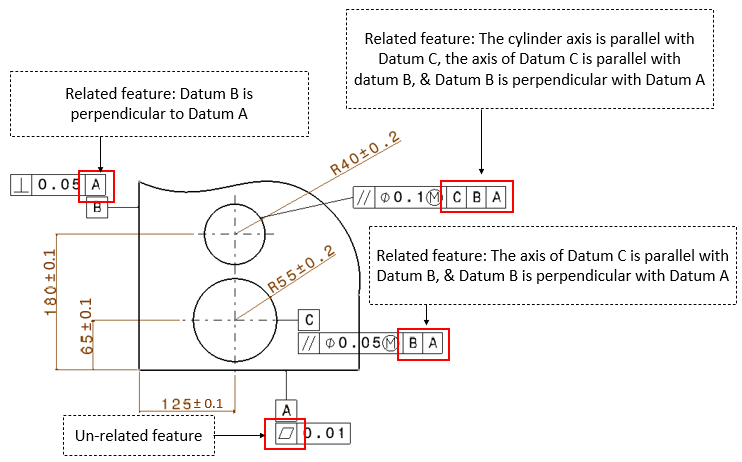
A deeper explanation of a datum system with an example is shown in figure 2 above. In figure 2, datum A is the main datum so that an un-related GD&T tolerance is applied, that is flatness.
Note that since datum A is the main and most important datum feature, the feature representing datum A should be accurately manufacture as high as possible. To control this, the tolerance value given on datum A is the tightest among other datums or feature tolerances.
For datum B and C, these datums have related tolerances. Because, there is datum A that can be used as the reference for both datum B and datum C.
Datum B is the second datum on the part (in figure 2 above) so that it has a reference only to datum A. meanwhile, datum C is the third datum on the part (in figure 2 above) so that datum C has two references, to datum B and then datum A.
For the small cylindrical features (in figure 2 above), the axis of the cylinder has a reference to all datum A, B and C.
It is important to note that the datum sequence in the GD&T symbols is related to the positioning sequence of the part on the table of a measuring machine (in case for inspection) or machine tool (in case for machining).
The explanation is as follow. For datum reference, the reading is from left-to-right. And for inspection or machining, the part positioning sequence should read the datum reference symbol from right-to-left.
For example, a datum symbol shows:
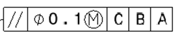
Hence, the reference for the parallelism tolerance (shown in the symbol above) should be read with respect to datum C, datum C with respect to datum B and datum B with respect to datum A.
For the placement of the part (for example in a measuring machine or machine tool base table), the placement sequence should be as follow. The part is placed on the machine base table starting from datum A, then datum B and then datum C.
Tolerance zone
Tolerance zone is a zone where the surface of a feature of interest lies within this zone. In general, tolerance zone can be in the form of:
- Line (straight or curve): a zone that is defined by two parallel lines or curves, such as straightness tolerance. The distance of the two lines or curves defines the tolerance value.
- Planar: a zone that is defined by two parallel planes. The distance of the two planes defines the tolerance value.
- Circular or cylindrical: a zone that is defined as two concentric circles or cylinders. The diameter difference of the two concentric features defines the tolerance value. The symbol should be preceded by $\varnothing$.
- Spherical: a zone that is defined as a sphere with a specific diameter that defines the tolerance value. The symbol should be preceded by $S\varnothing $.
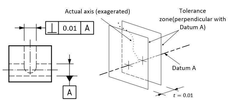
Some examples of these tolerance zone are as follows. In figure 3 below, the example of planar tolerance is shown for the perpendicularity tolerance of the axis of a slot feature. The tolerance zone is the distance of two parallel planes (figure 3 right) as far as 0.01 unit distance.
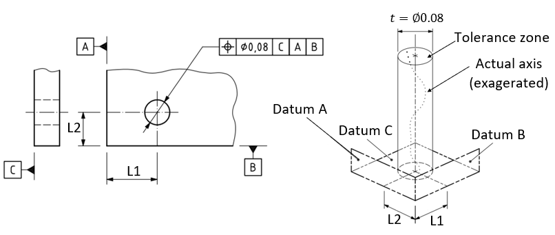
In figure 4, the example of cylindrical tolerance zone is given for the location tolerance of the axis of a hole. The tolerance zone is a hypothetical cylinder with diameter of 0.08 unit distance.
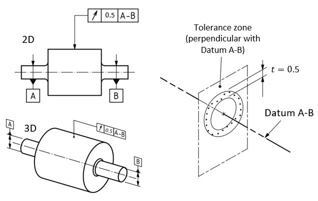
The example of circular tolerance zone is presented for the run-out tolerance of a slider cylinder (figure 5 below). The tolerance zone is the diameter difference between two concentric circles as much as 0.5 unit distance (figure 5 right).
For examples on how to read and interpret GD&T, readers can refer to this post. In this post, many more examples are given from a simple tolerance to complex tolerance on a part.
Material condition (MMC and LMC) and bonus tolerances
In GD&T or geometric tolerance, there are two important concepts that need to be understood: material condition and bonus tolerance.
These two concepts have a big role in an assembly process. In an inspection process where there is a bonus tolerance following the material condition requirement from the inspection process measurement, the number of non-conformance part can be reduced. Because, with a bonus tolerance, a component or part still can have more deviations larger than its tolerance limit shown in its technical drawing.
Material condition
Material condition is a condition where a feature of size is manufactured bigger or smaller than its nominal dimension. For example, a cylinder is made smaller than it should be or a hole is made larger than it should be. Nominal dimension is a value written in its technical drawing.
Material condition is only for feature of size, such as sphere and cylinder. The most common feature to be applied material condition (when the feature is toleranced) is cylinder.
There are two main important types of material conditions:
- Maximum material condition (MMC)
- Least material condition (LMC)
MMC is when a cylindrical pin or shaft is made at its maximum diameter (the largest pin or shaft) or when a hole is drilled at its smallest diameter (the smallest hole) according to their nominal dimension.
LMC is when a cylindrical pin or shaft is made at its minimum diameter (the smallest pin or shaft) or when a hole is drilled at its largest diameter (the largest hole) according to their nominal dimension.
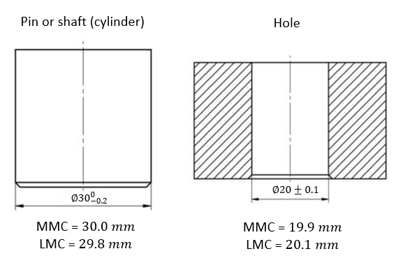
Figure 6 above shows the examples of MMC and LMC conditions on a pin and hole features. In figure 6 left, for the pin, its MMC is when the diameter is $30 mm$ and its LMC is when the diameter is $29.8 mm$. From figure 6 right, for the hole, its MMC is when the diameter is $19.9 mm$ and its LMC is when the diameter is $20.1 mm$.
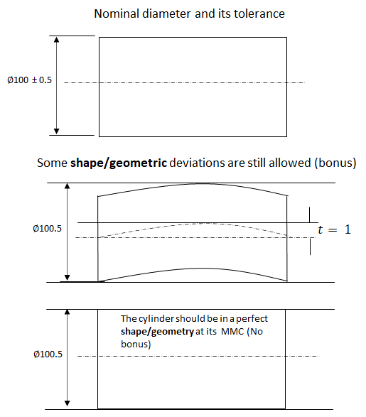
The illustration of MMC on a cylindrical pin and the implication of the MMC with regard to the real condition of the cylinder is presented in figure 7 above. In figure 7, it is shown that the cylinder is designed to have a diameter of $100\pm 0.5 mm$. Physically, the representation of the MMC of the cylinder is a hole where the pin is designed to be able to enter the hole to have a specific function, for example, to join two plates together.
With the stated nominal dimension, the MMC of the cylinder is 100+0.5=100.5 mm. In figure 7 (middle), when the cylinder is produced to be smaller than its nominal dimension = 100 mm and is still larger than the minimum tolerable diameter (99.5 mm), hence some shape deformations of the cylinder still can be allowed. These extra allowable shape deformations are called “bonus” (will be explained in a later section).
For example, if the cylinder is produced at diameter of 99.9 mm, hence the cylinder can have a shape deviation as much as 100.5-99.9=0.6 mm. As long as the cylinder (pin) does not have a deviation more than 0.6 mm, then the cylinder (pin) still can be inserted into the hole.
In figure 7 bottom, when the cylinder is produced at its MMC, that is at diameter of 100.5 mm, then the cylinder must have a perfect cylindrical form so that the cylinder can be inserted into the hole. In other words, no allowable deviation on the cylinder shape is permitted.
This “bonus” and MMC as well as LMC concept have a significant economic impact in the manufacturing cost of a component.
Bonus tolerance
Before we discuss “Bonus tolerance”, we need to understand the difference between the meaning of “MMC” and “MMC symbol”. That are:
- MMC means the smallest hole or the largest shaft or pin
- MMC symbol on a technical drawing means a bonus tolerance can be obtained if a feature of size is deviated from its MMC. For example, a hole is made larger than its minimum diameter or a shaft/pin is made smaller than its maximum diameter
The same applied for the meaning of “LMC” and “LMC symbol”. That are:
- LMC means the largest hole or the smallest shaft or pin
- LMC symbol on a technical drawing means a bonus tolerance can be obtained if a feature of size is deviated from its LMC. For example, a hole is made smaller than its maximum diameter or a shaft/pin is made larger than its minimum diameter
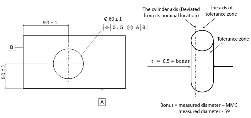
Figure 8 below shows the example of location tolerance of a hole with an MMC symbol. In Figure 8, the hole has a location tolerance as 0.5 mm with MMC symbol (written as “M”) and with respect to datum B and datum A. This MMC symbols means that if the hole is made larger that its minimum diameter (deviated from its MMC value), for example 60 mm (measured value) > 59 mm (its MMC value), then the axis of the hole can move as much as 0.5 mm due to bonus tolerance.
In this case, the bonus tolerance = measured diameter – MMC = 60-59 = 1 mm. Hence, the total tolerance zone size is 0.5 + 1 = 1.5 mm. This larger tolerance zone is because when the hole is made larger than its minimum diameter, if the hole axis shifts more than its allowable value (its location tolerance), then a pin designed to be able to go into the hole still can be fit in due to the larger hole.
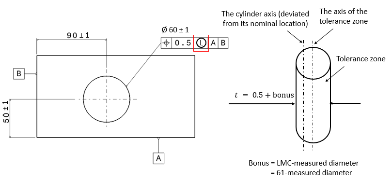
In figure 9 below, the example of location tolerance of a hole with an LMC symbol that is 0.5 mm with MMC symbol (written as “L”) and with respect to datum B and datum A. This LMC symbols means that if the hole is made smaller that its maximum diameter (deviated from its LMC value), for example 60 mm (measured value) < 61 mm (its LMC value), then the axis of the hole can move as much as 0.5 mm due to bonus tolerance.
In this case, the bonus tolerance = LMC- measured diameter = 61-60 = 1 mm. Hence, the total tolerance zone size is 0.5 + 1 = 1.5 mm. This larger tolerance zone is because when the hole is made smaller than its maximum diameter, if the hole axis shifts more than its allowable value (its location tolerance), then there will be more material on the hole to be machined, for example, to apply a finishing process to improve the surface quality of the hole.
Real examples of the advantages of applying MMC and LMC on feature of sizes (in this case a hole feature)
The advantage of using MMC symbol
MMC symbol is used to inform that a hole feature is designed to insert a bolt to join two plates. If the hole is made larger that its minimum allowable diameter (deviate from its MMC size), then the probability that a bolt can go into the hole becomes large as well. Because of this reason, there should be a bonus tolerance on the hole.
With the bonus tolerance, the probability of the hole to be rejected becomes small because the tolerance is relaxed during the verification of the hole feature in an inspection process. The reduce of part rejection will reduce scarp or rework cost and will reduce the total production cost of the part.
The advantage of using LMC symbol
LMC symbol is used to inform that some materials on a feature after manufacturing the feature should be preserved to allow further machining processes. For example, the excess material on a drilled hole can be finished with a subsequent boring process to improve the surface finish of the hole.
The explanation above show that when a hole is made smaller than its largest diameter. The hole still has some materials that allow further finishing processes applied to the hole. Hence, if the manufactured or drilled hole is deviated from its LMC size (drilled smaller than its LMC size), then the hole still has excess materials for further processing.
It is worth to note that, although bonus tolerance has some benefits, it also has a drawback. Bonus tolerances will increase variation sources on a final assembled product. In 3D tolerance stack-up analysis (including 2D tolerance analysis), bonus tolerances will add more variations to the total variation chain of an assembly.
Conclusion
From the explanation about the GD&T and its element in this post, it can be seen that GD&T symbols (tolerances) have a very deep meaning and explanation. Those GD&T symbols are designed to accommodate the design intention of a mechanical designer to a manufacturing and quality inspection engineer.
The concept of material condition (both MMC and LMC) are presented in detail with examples. These material conditions cause bonus tolerances when verifying the conformance or non-conformance of a geometric tolerance on a part.
Particularly for bonus tolerance, this bonus has a significant impact on the total cost of an inspection process and hence to the total cost of a production process.
Finally, it is worth to note that GD&T does not replace traditional “+/-” tolerance. But, GD&T complements the traditional tolerance.
We sell tutorials (containing PDF files, MATLAB scripts and CAD files) about 3D tolerance stack-up analysis based on statistical method (Monte-Carlo/MC Simulation).