Low frequency radio navigation system for use in natural disaster situations
It is critical to have a navigation system for search and rescue of victims and important assets in a disaster situation.
It is critical to have a navigation system for search and rescue of victims and important assets in a disaster situation.
This post is based on a paper “Low RF-based Navigation for Emergencies in Difficult Environments”. All details can be found in the paper [1].
Both terrestrial and global navigation satellite system (GNSS) infrastructures have limitations for use as a navigation tool in a disaster situation.
In this post, we will present and discuss what the limitations of these two systems are and discuss a solution for navigation in such disaster environment.

Motivation: Navigation in disaster environments
In a disaster or hostile environments, such as after earthquake, flood, volcano or storm phenomena, common wireless communication system infrastructures are prone to destruction. For example, cellular network and other terrestrial communication system as well as supporting infrastructures, such as electricity supply, can be destroyed due to a natural disaster.
Due to the destruction, these communication systems cannot function properly for communication and also for navigation.
One simple communication system that can be used in disaster environment is walkie-talkie. This device is battery operated and is portable. However, this device cannot provide a navigation functionality.
Navigation functionality is needed in disaster environment. For example, to find victims or critical assets in a wrecked building, a rescue team need to carry a navigation system to guide them finding the victims or assets.
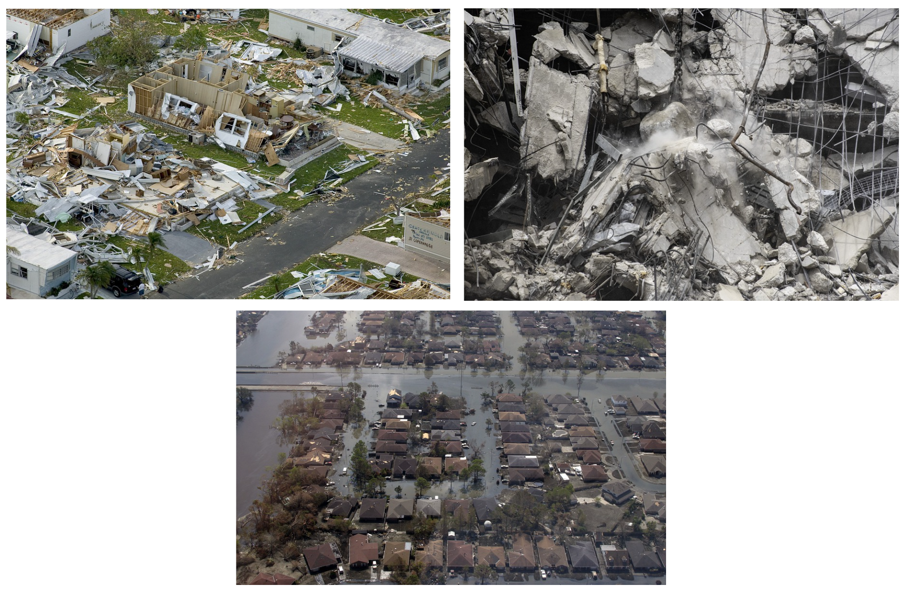
Figure 1 below shows some examples of disaster environment or emergency conditions, such as wrecked buildings due to tornado and earthquake as well as destroyed buildings or houses due to flood.
GNSS system can provide global navigation that can be accessed anywhere and GNSS infrastructure is free from disasters occurring on earth. However, the signal power of received GNSS signals are very weak due to the signals come from satellites, typically about 23000 km above the earth (the height of medium-earth orbit satellite).
Also, since the transmission frequency used by GNSS system is very high at GHz level (for example GPS L1 and GALILEO E1 signals are transmitted at 1575.42 MHz), the propagation power of GNSS signals to penetrate obstacles, such as walls of a building, is low.
Based on the disadvantages of terrestrial and GNSS radio frequency (RF) transmission, a radio navigation system using low frequency transmission is developed. The main idea of the system is that it uses low radio frequency transmission (sub-GHz) to have a high propagation power and transmits ranging signal for navigation.
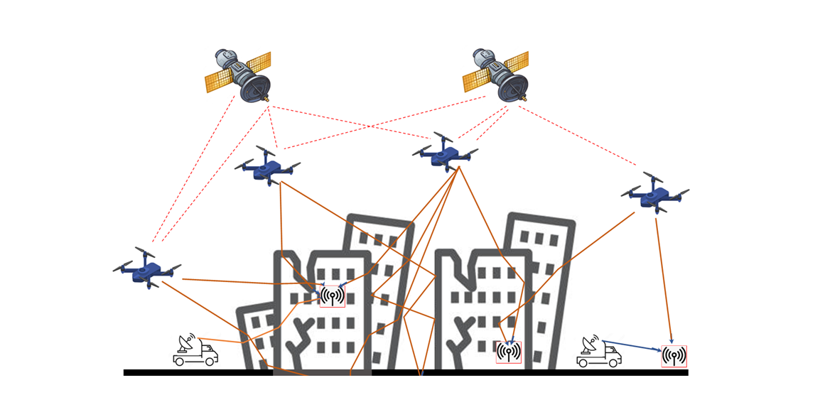
Figure 2 below shows the final goal of the low frequency system to provide radio navigations in disaster environment.
In figure 2, the main unit of the system is a transmission (Tx) unit. The Tx unit should be compact and portable and battery-operated. Because, the Tx unit will be mounted on a moving vehicle, especially drones.
The Tx unit receives its position from open-sky GNSS signals and re-transmits its position and ranging signals to a receiver (Rx) unit located in obstacle environments such as wrecked buildings. That is, the Tx signal should be able to perform outdoor-to-indoor transmission.
Based on the Tx position and range, the Rx unit can estimate its position.
Similar to GNSS positioning, the low frequency radio navigation system requires at least four Tx units (four drones) to be able to robustly estimate the position of the Rx unit.
In addition, the Tx unit of the system implements a GPS L1 like direct sequence spread-spectrum ranging signals with low number of message bits to reduce computational demands and energy use (prolong the battery usage).
READ MORE: Generating GPS L1 C/A pseudo-random noise (PRN) code with MATLAB and C/C++.
RF signal propagation in cluttered area or through obstacles
Radio frequency (RF) signals will be attenuated when the signals travel via an obstacle. Theoretically, the lower the transmission frequency, the higher the RF signal propagation capability.
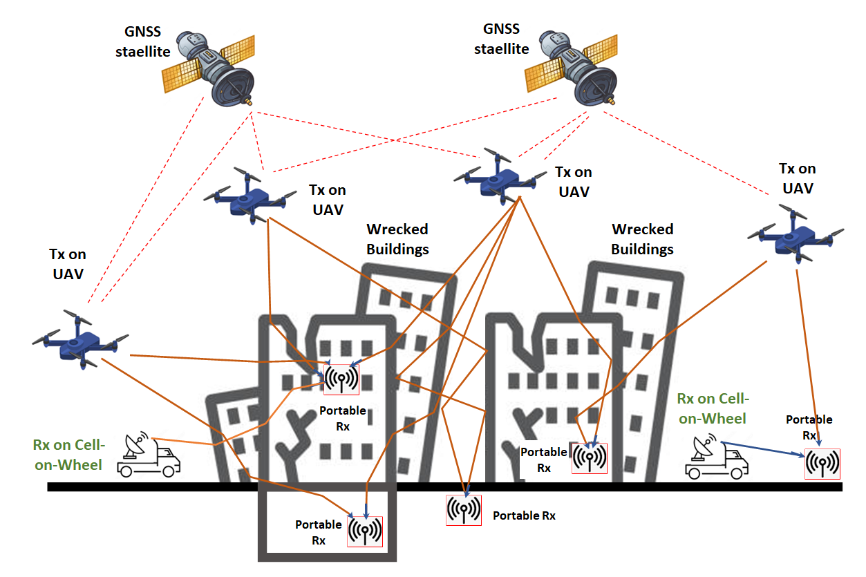
Figure 3 below shows the schematic view of signal propagation mechanisms in cluttered environment with obstacles. In figure 3, propagation losses can be caused by the walls, windows and doors of buildings, trees and other obstacles.
In general, the higher the Tx unit height above the ground, the less obstacles it will have and the less signal propagation loss it will experience.
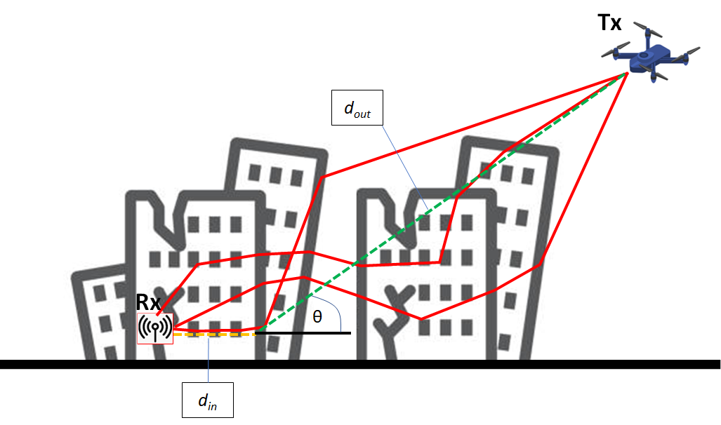
The main propagation loss due to obstacles experienced by transmitted signals from a Tx unit are classified into several conditions, that are:
- Propagation loss due to propagation in-between buildings or houses or trees
- Propagation loss due to propagation above the rooftops of buildings or houses
- Propagation loss through low-attenuating window and grazing incident angle
- Propagation loss due to guided indoor propagation and walls/doors/multi-floor openings
The total propagation-loss $PL_{out-to-in}$ of an outdoor-to-indoor transmission is formulated as:

Where:
- $PL_{out}$ is the total propagation loss for outdoor-to-outdoor transmission and is a function of Tx height $h_{TX}$, Rx height $h_{RX}$, the linear distance from the Tx to an incident point of a building $d_{out}$ and transmission frequency $f$.
- $L_{BEL}$ is the propagation loss for outdoor-to-indoor transmission and is a function of building materials $B_{m}$, transmission frequency $f$ and incident angle $\theta$.
- $PL_{in}$ is the propagation loss for indoor-to-indoor transmission and is a function of the linear distance from the incident point on the building to the Rx unit $d_{in}$ and number of openings $n_{walls}$, such as doors, corridors and walls.
It is important to note that different building materials will significantly affect the propagation loss of RF signals when by passing the wall of buildings. In addition, the propagation loss is also affected by the RF frequency.
Low frequency radio navigation system (LowRF) development
The development of the low frequency radio navigation system is based on commercial high-grade software defined radio (SDR) from Ettus. For the Tx unit USRP E312 is used. Meanwhile, for the Rx unit, USRP X310 is used.
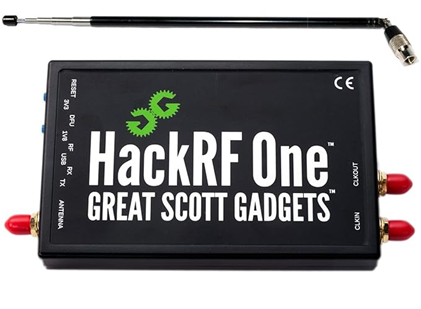
However, the low frequency system can be built by using any other sufficient SDR instruments with low cost, such as Hack-RF SDR. This HACK-RF is well-known and readily available for home use and for hobbyist with community supported opensource software.
The E312 used as the Tx unit is a battery-operated SDR system having a compact size. This E312 Tx unit can be mounted onto a medium size drone with payload of around 0.8 Kg.
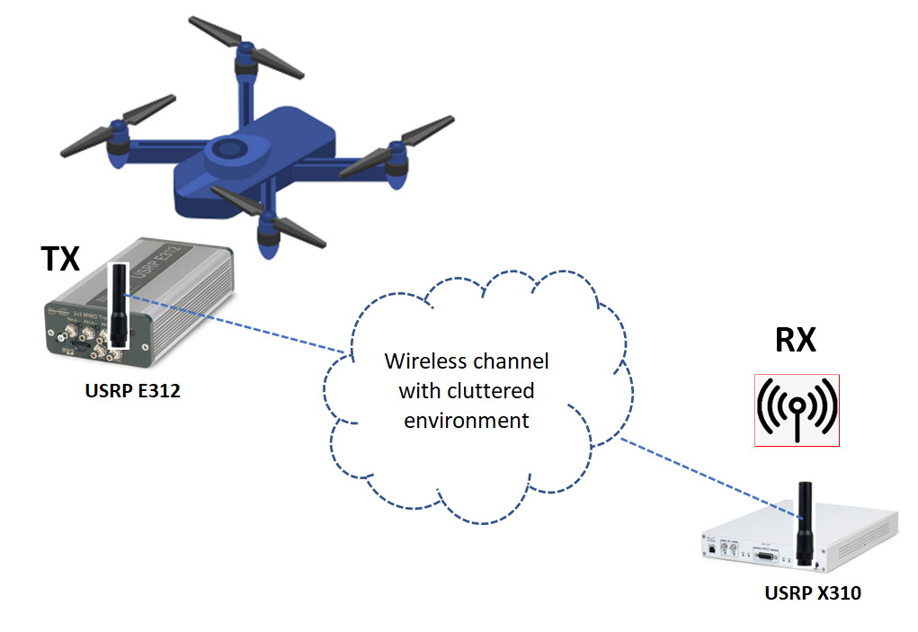
Figure 4 below shows the schematic view of the low radio frequency navigation system.
In figure 4, the Tx unit is mounted on a drone so that the Tx unit can get open-sky GNSS signals and construct its coordinate to send to the Rx unit. The Tx unit is battery operated and has an integrated computer to process and generate ranging signals with messages containing the Tx position.
The X310 Rx unit is a high-grade SDR receiver to receive the signal form the Tx unit. Special for Rx unit, even a low-grade SDR can be used since the signal processing will be performed in a computer that can be in small or compact size.
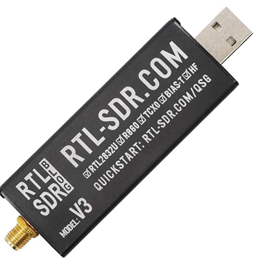
Any SDR with at least 2 MHz sampling rate capability will be sufficient to be used as the Rx unit of the system, for example, RTL-SDR.
The Rx unit is meant to be inside buildings since its main goal is to locate victims or assets in building or obstacle environments.
The transmitted message sent by the Tx unit contains 200 bits. This message contains pseudorandom number (PRN) code as well as the position and velocity of the Tx unit mounted on a drone.
The software development in the E312 Tx unit use USRP UHD 4.0 libraries with RFNOC 4 framework.
READ MORE: TUTORIAL: RFNoC 4 environment development setup for USRP devices.
The main transmission frequency used in the implementation of the system is 500 Mhz. The antenna used for the system is a low-cost of-the-self antenna with operating bandwidth of 400 MHz-500 MHz.
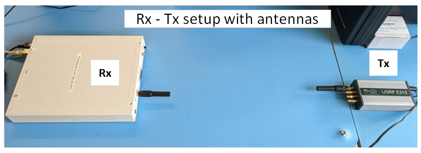
Figure 5 below shows the implementation of the Tx unit with USRP E312 and the Rx unit with USRP X310. In figure 5, initial test of the system is performed to test the signal operability and the signal processing at the receiver side. The test is performed in a laboratory.
From the test, the receiver can get the code delay to be converted for ranging and the position of the Rx unit.
In figure 5 for the initial laboratory test, both Rx and Tx units are static. However, Doppler frequency shift is observed at the Rx side. This Doppler shift is due to the TCXO clock drift of the receiver that is usually 1-2 ppm of the frequency, that is around 500 Hz – 75- Hz Doppler shift.
Detailed system designed and implementation can be found in [1].
READ MORE: GNSS spoofing: a fatal attack on GNSS system that is difficult to detect.
Low RF navigation system field testing
After testing the functionality of the Tx and Rx units in the laboratory. Two real tests, also operating at 500 MHz frequency, are performed.
The two tests are as follow.
The Tx and Rx unit are both in the same building but in different rooms
The Tx unit and Rx unit is separated for about 10 m. Since the Tx and Rx units are placed in different rooms, transmitted signals will experience obstacle and multipath.
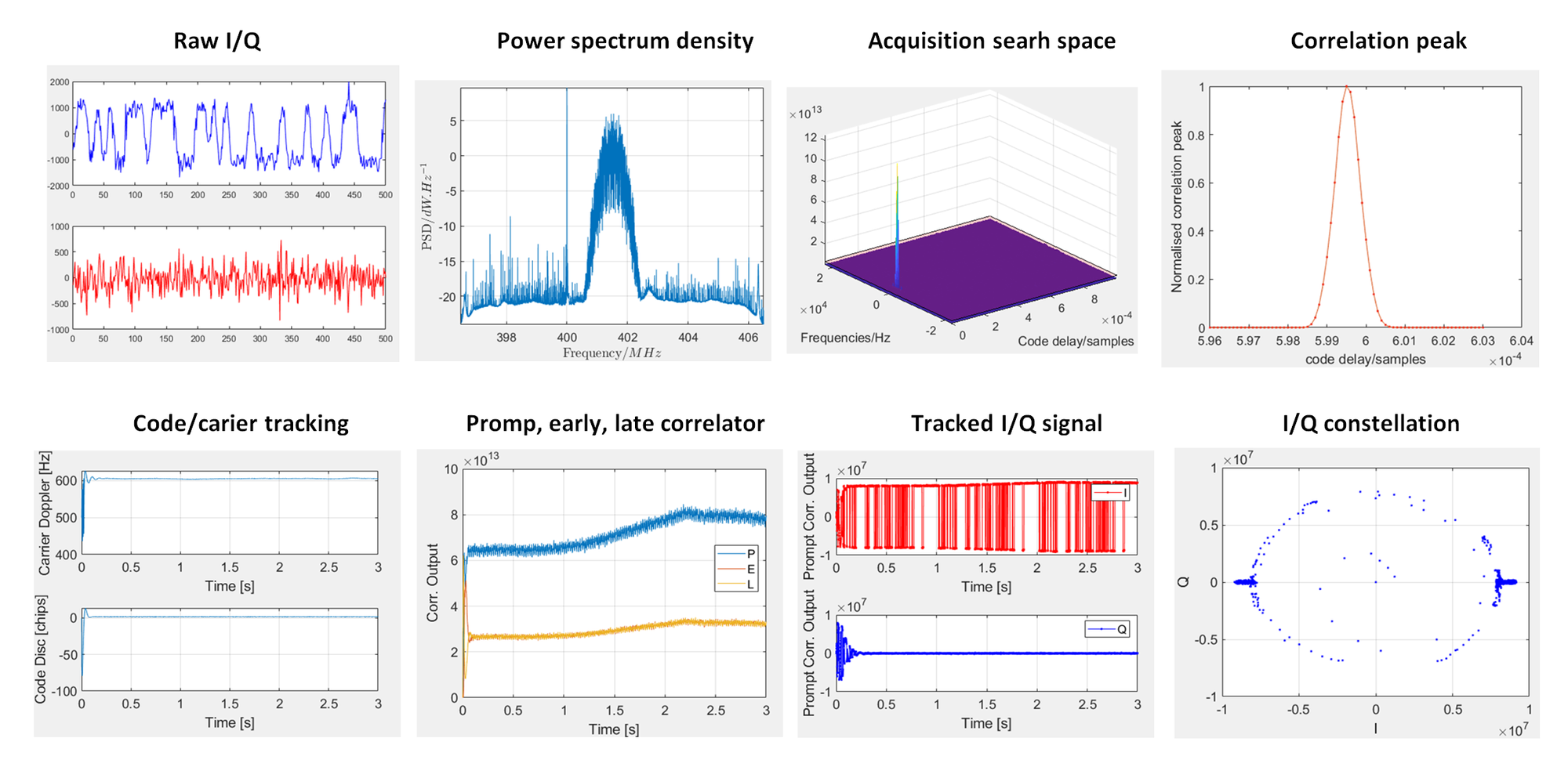
Figure 6 below shows the received signals at the Rx unit and the signal evolution in different processing stage: acquisition and tracking.
From figure 6, the raw I/Q signals are distorted due to channel impairments (multipath and obstacles). However, good acquisition can be obtained as the signal peak can be distinctively observed and the correlation peak shows a near perfect triangle shape.
From figure 6, the signal can be tracked by observing the IQ constellation plot is clustered in two groups around ‘+’ and ‘-‘ values at the I-axis and around ‘0’ values at the Q-axis.
Also, we can observe that the tracked I signal have a rectangular shape representing data bits and the tracked Q signal mostly contains noise centred at zero value. From the tracked I signal, message bit demodulation can be successfully performed.
The Tx is mounted on a drone (outdoor) and the Rx is inside a building
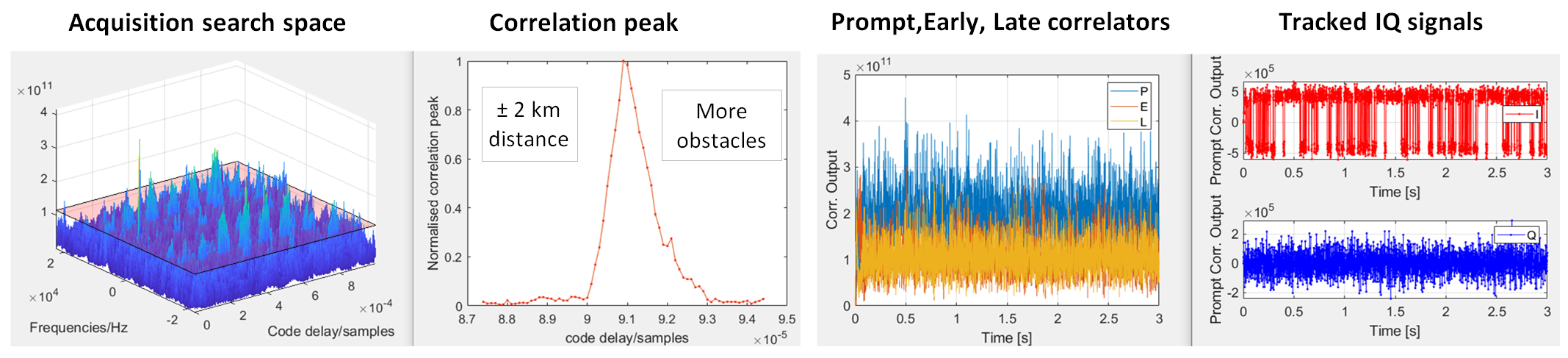
In this test, the Tx unit is outdoor and is mounted on a drone. The drone is around 20 m height above the ground. Meanwhile, the Rx unit is placed inside a building.
Since the distance between Tx and Rx is about 2 km and the drone height is quite low, this transmission is more challenging then at the first case presented above.
More obstacles will affect the transmission, especially from trees and other infrastructures (other surrounding buildings and cars).
Figure 7 below shows the signal acquisition and tracking processes of received signals by the Tx unit inside the building.
From figure 7, we can see clearly that more noises on the acquisition search space are obtained. The noises are due to more obstacles causing high propagation losses of the transmitted signals.
The correlation peak in figure 7 has a not-near perfect triangle shape (compared to the one in figure 6). As expected, the noise effects become significant in this type of transmission test.
From the tracking process (figure 7), the data or message bit of the signals can be recovered. The tracked I channel shows rectangular shapes representing the data or message bit. Meanwhile, the tracked Q channel only shows noise centred at zero values. Hence, message bit demodulation processes can be successfully performed from this tracked I signal,
From these results, the developed system shows promising results to be use for radio navigation system in disaster environments.
Conclusion
A low frequency radio navigation (LowRF) system specifically designed for disaster environment has been presented and discussed in this post.
In disaster environment, a navigation functionality is needed for search and rescue operations to find victims and critical assets, for example, inside a wrecked or destroyed buildings.
Common wireless communication system infrastructures are prone to destruction and become unavailable in disaster environments. Other available communication systems, such as walkie talkie, cannot provide navigation services.
The low frequency radio navigation system can provide navigation functionalities in disaster environment, for example, navigation into wrecked buildings.
One of the main features of the low frequency system is that it has a high signal penetration power due to its low frequency (sub-GHz) transmission. In addition, the system transmits ranging signal containing position data of the transmitter.
References
[1] Syam, W. P., Scott, D., Conesa, A. Pérez, Rodríguez, I., López, M., Juan, E., Ioannidis, R. T., "Low RF-Based Navigation for Emergencies in Difficult Environments," Proceedings of the 35th International Technical Meeting of the Satellite Division of The Institute of Navigation (ION GNSS+ 2022), Denver, Colorado, September 2022, pp. 1729-1745.
https://doi.org/10.33012/2022.18499
You may find some interesting items by shopping here.