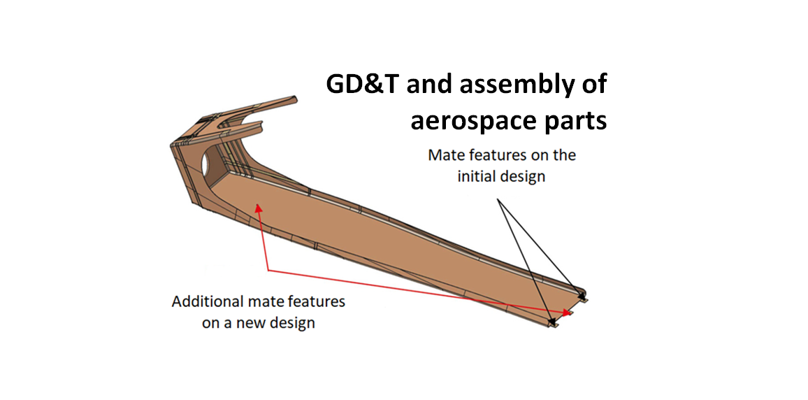
Geometric dimensioning and tolerancing (GD&T) and assembly of aerospace parts
The assembly feature design and tolerance stack-up analysis of aerospace parts are very important for the analysis of assembly variations or deviations.
The assembly feature design and tolerance stack-up analysis of aerospace parts are very important for the analysis of assembly variations or deviations. Because any small deviations on aerospace parts on, for example, the wing parts or engine parts, will be propagated to the assembly variations and then will significantly affect the performance or maybe the safety of an aeroplane.
Not only performance and safety, but also the reliability of the components will be degraded as well and cause the increase on their maintenance cost.
Hence, each design, manufacturing process and assembly process of aerospace components should be carefully and correctly designed and planned.
In this post, we will discuss various aspect of GD&T and assembly for aerospace components. At the end of this post, we can appreciate the importance of assembly feature design and geometric dimensioning and tolerancing (GD&T) for aerospace components.
READ MORE: 3D tolerance stack-up analysis with examples
The importance of mate feature on aerospace component design
Like any design of parts, such as automotive car body parts and rigid parts, mate features should be designed correctly to reduce the use of fixture on the assembly process of the parts of an aeroplane.
By reducing the use of fixture, the complexity of the assembly and variation of the assembly can be significantly reduced and hence the cost of the assembly can be minimised as well.
Figure 1 below shows the example of the importance of mate features (in the form of slot and hole) to be correctly designed and located on aeroplane parts to assure that the assembly key characteristic (KC) can be satisfied and the variations are within tolerance. The KC in this case is the gap between the top skin and the bottom skin.
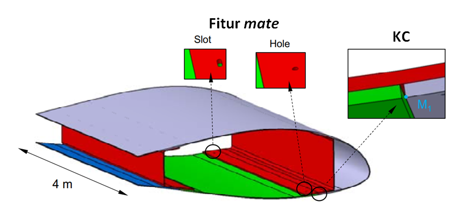
In addition, the tolerance chain used for the tolerance stack-up analysis should consider the manufacturing or process fingerprint that is unique to a specific manufacturing process. For example, in a drilling process, the location variation will be common and have pronounce fingerprint toward the location of mate features (holes) of aeroplane components. The variation of the drilled hole location will directly translate to the variation of the assembly process.
READ MORE: Understanding fundamental assembly features: Mate and contact features
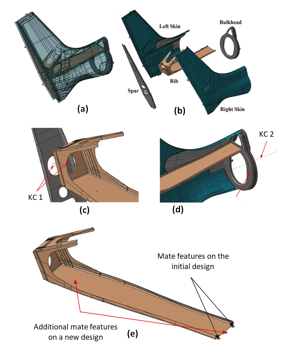
Another example of the importance of mate feature is on the design of a helicopter tail assembly (see figure 2 below).
Figure 2a shows the complete assembly of the helicopter tail and figure 2b presents all the components constituting the helicopter tail assembly.
Figure 2c and figure 2d show the KC definitions for the tail assembly, that is KC1 and KC2 that should be controlled so that their geometrical variations are within their allowable tolerance.
KC1 is the parallelism between the rib and spar components and KC2 is the perpendicularity between the axis of the helicopter tail and the planar surface on the bulkhead. From these two KCs, it can be observed that the rib components are the most vital component that constructs the helicopter tail assembly.
Figure 2e presents the difference between the initial design and the new (revised) design of the rib component. On the initial design, the number of mate features is only two on one of the edges of the rib component. Due to only these two mate features, that are not constraining all the movements, the locating and orienting the rib with respect to other parts of the assembly will be not accurate due to high position variation. This high position variation will propagate and cause a large variation on the two KCs.
The solution is by adding two additional mate features placed on the other edge of the rib part (see figure 2e). With these additional mate features (that can constraint completely the movement), the locating and orienting of the rib component with respect to the other parts will be deterministic (low positioning variations) and hence will significantly reduce the variation on the two KCs.
READ MORE: Assembly and tolerancing
The effect of geometrical variations on the performance of an aerospace component
Other interesting examples that show how important GD&T and tolerance stack-up analysis on the assembly of an Aeroplane engine and wing will be presented.
Figure 3 below shows a case study of the assembly of the rear turbine assembly of a turbo-fan jet engine. Figure 3a and figure 3b present the position of the rear turbine assembly with respect to the overall turbo-fan engine jet assembly (red coloured).
Figure 3c shows the detailed analysis of the flow and structural stress of the rear turbine assembly. Figure 3d and figure 3e show the effect of geometrical variations on the rear turbine assembly with respect to the air flow passing the rear turbine and on the stress distribution on the rear turbine components, respectively.
In figure 3d, it can be observed that a small geometrical variation on the rear turbine will significantly change the property of the air flow from laminar into turbulent flow. In figure 3e, it can be observed that the geometrical variation will significantly affect the stress concentration on the rear turbine that can reduce the reliability of the component.
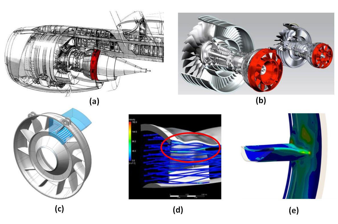
Figure 4 below shows another example for the assembly of the wing of an aeroplane. From figure 4, the design of the parts for rib and skin and their tolerance are presented.
On the wing assembly, the important factor is to control the shape of the skin profile. Because the skin profile significantly affects the air flow passing the skin.
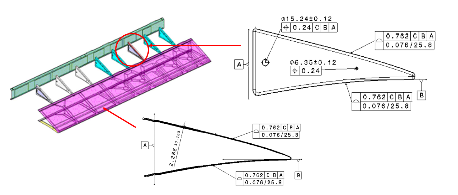
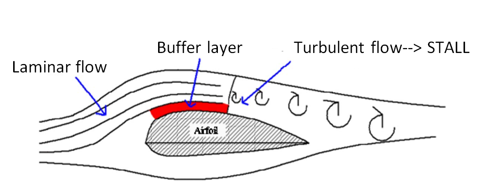
Figure 5 below presents the effect of the skin profile variations on the shape of the air flow passing the skin. From figure 5, it can be seen that if the skin profile deviation is outside its tolerance value, the air flow passing the skin becomes turbulent. This turbulent air will reduce the lifting force produced by the wing and can cause the airplane to stall.
READ MORE: The economic benefits of tolerance stack-up analysis
Conclusion
In this post, various examples of the importance of GD&T, tolerance stack-up analysis and assembly feature design on aerospace components have been discussed.
From those various examples, we can see that an assembly process is a complex activity and vital to produce a high-quality product. To produce a high-quality product, the design of parts, the manufacturing processes, the assembly process until the inspection processes should be correct as well as efficient.
The analysis of tolerance stack-up is one of the most vital tools that can be used to verify the design of an assembly and to analyse the effect of geometrical variations of parts that construct the assembly.
Finally, it is hoped that by reading this post, readers can appreciate the importance of assembly design and analysis.
READ MORE: Geometric dimensioning and tolerancing (GD&T)
References
[1] Bacharoudis, K., Bakker, O.J., Popov, A. and Ratchev, S., 2018. Trade-off study of a variation aware determinate wing assembly against a traditional assembly strategy. In MATEC Web of Conferences (Vol. 233, p. 00008). EDP Sciences.
[2] Corrado, A. and Polini, W., 2017. Assembly design in aeronautic field: From assembly jigs to tolerance analysis. Proceedings of the Institution of Mechanical Engineers, Part B: Journal of Engineering Manufacture, 231(14), pp.2652-2663.
[3] Forslund, A., Madrid, J., Lööf, J. and Söderberg, R., 2016. Robust design of aero engine structures: Transferring form error data when mapping out design spaces for new turbine components. Procedia CIRP, 43, pp.47-51.
[4] Forslund, A., Madrid, J., Söderberg, R., Isaksson, O., Lööf, J. and Frey, D., 2018. Evaluating how functional performance in aerospace components is affected by geometric variation. SAE International Journal of Aerospace, 11(1), p.5.
[5] Polini, W., Marrocu, M. and D’Ambrosio, L., 2007. Tolerance analysis of free-form surfaces in composite material.
You may find some interesting items by shopping here.