Inspection of geometric tolerances: GO and NOGO gaging system
In this post, we will discuss and understand the concept of GO and NOGO gage to verify geometric tolerance of positions and be able to design these types of gaging system.
Geometric tolerancing controls the whole shape of a feature and complements the traditional plus-minus (traditional) dimensional tolerance to remove ambiguity in tolerance interpretations.
In this post, we will discuss and understand the concept of GO and NOGO gage to verify geometric tolerance of positions and be able to design these types of gaging system.
Coordinate measuring machine (CMM) is a well-known measuring instrument to verify many geometric tolerance types.
However, CMM is relatively slow and unsuitable for a large volume component inspection task.
For fast geometric tolerance inspection of mass-produced components, in shop floors, we use gaging system: functional gage such as GO gage and NOGO gage.
Functional gage is a tool to quickly check if a part can function properly or not based on the part’s tolerance. GO and NOGO gage are most used types of functional gage.
Unlike with CMM measurements, the idea GO and NOGO (functional) gages is to only check whether a produced part can satisfy its function or not instead of to accurately quantify the geometrical deviation [1].
By only checking the functionality of the part, the GO and NOGO gage can inspect parts quickly and is suitable for mass and in-line part inspection in a shop floor.
Let’s go into the discussion.
READ MORE: Examples on how to interpret GD&T: Form, orientation, location and run-out tolerances
Virtual condition for material modifiers (MMC and LMC)
Functional gage verifies the functionality of a feature by checking whether the feature satisfies its virtual condition acceptance boundary or limit.
Virtual condition specifies the worst-scenario of a size feature by considering both the feature’s size (plus-minus) tolerance and any geometric tolerances that affect the feature’s size.
That is, in another word, virtual condition is an envelope boundary that a feature can fit and still meet its mating requirements.
Functional gage (for example GO and NOGO gages) represents the size of the virtual condition of a feature of size.
The dimension or size of a functional gage follow the size of the virtual condition of a feature of size to check, which are:
- An external feature must fit into an internal gage element, or
- An internal feature of size must fit around an external gage element.
The concept of virtual condition is only relevant when modifier maximum material conditions (MMC) and least material conditions (LMC) are called out in GD&T symbols.
The formula to calculate the virtual condition for both feature of size with MMC and LMC modifiers are as follows:
- Virtual condition internal feature (such as hole):
For MMC case: MMC (smallest size) – geometric (e.g., position) tolerance.
For LMC case: LMC (largest size) + geometric (e.g., position) tolerance.
- Virtual condition external feature (such as pin/shaft):
For MMC case: MMC (largest size) + geometric (e.g., position) tolerance.
For LMC case: LMC (smallest size) - geometric (e.g., position) tolerance.
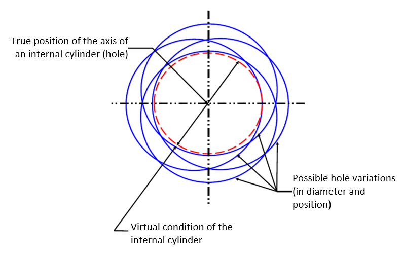
Figure 1 below shows the illustration of the virtual condition of an internal cylindrical feature with MMC modifiers for position tolerance. In this figure, the blue circles are various possible diameter (and shape) of the cylindrical features.
Meanwhile, the red circle is the cylindrical features’ virtual condition. This virtual condition represents the allowable smallest diameter (as an internal cylinder with MMC case) considering the smallest allowable diameter minus its position (geometric) tolerance.
If the cylindrical feature is made smaller than this virtual condition diameter, hence we can assure that the hole cannot meet its mating requirements to fit a pin into the cylindrical hole.
For the case of an external cylindrical feature (such as pin/shaft), figure 2 below shows the virtual condition of an external cylinder with straightness tolerance and MMC modifiers.
Figure 2-left shows the straightness tolerance specification for the pin/shaft and figure 2-rigth shows the virtual condition of the features and possible cylindrical shape variations within the virtual condition limit.
In this example, the allowable cylinder diameter is between 24.8mm and 25mm with straightness tolerance of 0.1mm and MMC modifier.
The virtual condition for this case is the MMC size + straightness tolerance = 25mm+0.1mm = 25.1mm.
This straightness tolerance implies that at MMC, when the diameter is at maximum allowable 25.1mm, the cylinder shape should be in perfect shape (perfect shape at MMC).
Any shape variations will cause some of the cylinder surface is outside the virtual condition, meaning the cylindrical part will not satisfy its functional requirement.
Otherwise, when the cylinder diameter is less than 25.1mm and above or equal to 24.8mm, there will be some tolerable part shape variations where the cylinder can still satisfy its functional requirements.

READ MORE: Datum references, tolerance zone and material condition in GD&T
Geometric tolerance inspection by GO gage system
The main aim of GO gage is to verify geometric tolerances with MMC modifiers [2].
We design feature of sizes (such as pin and hole) having geometrical tolerances with MMC modifiers commonly to have functions as part mating.
Meaning, we want the feature can mate with its counterpart features.
For example, when we design a hole, very often we want the hole just enough to insert a pin to joint two parts at a correct position.
Based on this function, we design and use GO gage to quickly check whether a hole on a part can accommodate its counterpart pin without needing to know exactly how big the hole shape variation is.
For this hole verification, the GO gage will be the shape of its counterpart pin. The size of the pin represents the virtual condition of the hole to check. If the pin can go into the hole, it means that the hole satisfies its intended function.
For example, a hole with diameter of 10mm-11mm with positional tolerance of 0.1mm with MMC modifier. Hence the size of the GO pin gage is 10mm-0.1mm = 9.9mm.
And vice versa, if a feature to check is a pin. Then, the GO gage is a hole with size of the virtual condition of the pin.
In summary, GO gage means that the gage should go into or go around a feature to check. If the GO gage cannot go into or go around a feature to check, hence the feature cannot satisfy its function.
READ MORE: 3D tolerance stack-up analysis with examples
Geometric tolerance inspection by NOGO gage system
The main aim of NOGO gage is to verify geometric tolerances with LMC modifiers [2].
Features of size with LMC modifiers usually have purposes to keep some materials for further processing, such as machined finishing processing (facing, boring, face milling and other operations).
For example, we drill a hole to be smaller than the hole nominal dimensions. Because we want to keep some materials for boring process to make the hole surface smooth and achieve its final diameter accurately.
Another example is we mill process a slot feature to have a smaller width than its final widths so that we can implement further finishing milling process to get a slot with high accuracy and good surface finish.
Let’s say we have a hole with nominal dimension of 10mm-11mm with cylindricity tolerance of 0.1mm with LMC modifier.
The NOGO gage for this hole is a pin with diameter size of the virtual condition of the hole. That is, the NOGO pin gage should have diameter of 11mm+0.1mm = 11.1mm. If the pin can go into the hole, it means that no material left for the hole for further finishing process and hence the hole does not satisfy its designed function.
In summary, NOGO gage means that the gage should NOT go into or go around a feature to check. If the NOGO gage can go into or go around a feature to check, hence the feature cannot satisfy its function.
READ MORE: 2D tolerance stack-up analysis with examples
A practical example of designing a GO gage
Brief introduction
In summary, the basic ideal premise of gaging system is to reject all bad parts (those do not satisfy tolerances) and to accept all good parts (those satisfy tolerances).
However, in real situations gaging itself has geometrical error due to manufacturing processes and also environmental effects such as thermal expansion.
That is why we also need to design and tolerance a gaging system!
Due to the imperfections of a gage, in inspection process, there will be a possibility that we will reject good parts (technically in-tolerance) or accept bad parts (technically out-of-tolerance) when the parts are at their borderline (when the part geometrical errors are at the boundary of the tolerances).
In this situation, our organisations must decided what error we are willing to accept and what error we cannot accept. That is, our company must decide whether we will allow some bad parts to be delivered to customers (accept some bad parts) or we never tolerate any bad parts being delivered to customers (accept to reject some good parts).
Let’s say we have a hole to inspect.
If we decide to reject some good parts to make sure we never deliver bad parts. Hence, our GO pin gage will have dimension of the MMC of the hole to check and with only positive tolerance.
This means that the GO pin gage will only made equal or larger than its nominal dimension such that some functional hole at the borderline may be rejected. This policy will cause our part quality high but also increasing production cost due to increase in repair or scrap.
If we decide to accept some bad parts being delivered to customers. Hence, our GO pin gage will have dimension of the MMC of a hole to check with only negative tolerance. That is, we only produce the GO pin gage with equal to smaller than its nominal dimension.
This policy will cause we accept some bad parts at the borderline. Hence, we will reduce manufacturing cost of the hole at the expense of decreasing part quality.
Based on ASME Y14.43[2], there are two main policies for gaging tolerancing:
- Absolute gage tolerancing (pessimistic)
- Practical absolute gage tolerancing
Particularly, for GO gage, we prefer to use the absolute gage tolerancing policy such that we never accept bad parts with the expense of rejecting some good parts.
Because we want to never accept out-of-tolerance part for GO gage verification process due to its part mating importance.
Next, we will go into the GO gage design case study.
Practical example of GO gage design
The most common GD&T application in mechanical assembly is position tolerance.
In this example, we will design a GO gage to inspect the functionality of hole features on a part or workpiece.
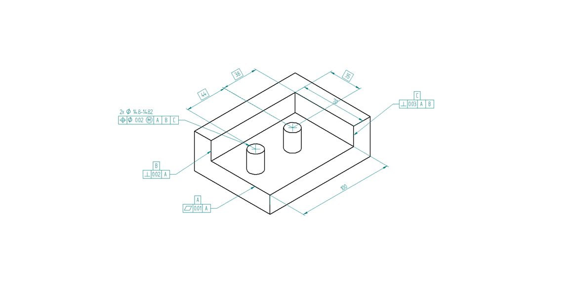
Figure 3 below shows a part having two-hole features with position tolerance and MMC modifier. These features need to be quickly inspected for its functionality by using a GO pin gage.
The main function of the holes is to accommodate pin for assembly with its counterparts.
The holes have nominal diameter of 15mm with size tolerance of 0mm-0.02mm. The geometrical tolerance for the holes is position tolerance of 0.2mm with MMC modifiers with respect of Datum A, B and C.
The positions of the holes have true position of 35mm from the top side and 38mm and (44+38)mm = 82mm from the right side.
The datum feature A is the top surface of the part. Meanwhile, the datum feature B and C are the long side and short side surface of the part respectively.
Datum feature A (since it is the primary datum) has an unrelated flatness tolerance of 0.1mm. Meanwhile, datum feature B has perpendicularity tolerance of 0.2mm with respect to datum A and datum feature C has perpendicularity tolerance of 0.3mm with respect to datum A and B.
Note that, datum feature A has the stringent tolerance since this datum is the primary datum where all tolerances refer to.

Figure 4 below describes the design of the GO gage for the part. In this figure, the GO gage has two pins gage to check the hole position as well as datum feature simulator to locate the part when we perform the gaging (inspection) process.
In short, the GO gage has the “negative shape of the part”.
The design specification of the GO gage are as follows:
- The geometrical tolerance of the gage features, such as datum simulator and the pin are 10% of the tolerance of the par.
This implies that the GO gage must be much more accurate than the part to check to make the inspection process meaningful.
In addition to high accuracy, the material of the GO gage should have higher thermal stability than the material of the part to make sure there is no long-term deformation of the GO gage.
Any geometrical deviation and deformation of the GO gage will increase probability to reject good parts and accept bad parts!
- The size tolerance of the dimension of the pin of the GO gage is 14.8mm-14.82mm following the absolute gage tolerancing (pessimistic) policy to make sure we do not pass any bad parts.
The value 14.8mm dimension is calculated as the virtual condition of the hole (MMC-position tolerance) and we set the dimension tolerance to be +0.02mm to make sure we do not pass bad parts.
- The position tolerance of the pin is 0.02mm with MMC modifiers. Meanwhile the geometrical tolerance for the datum feature simulator A, B and C are 0.01mm (flatness), 0.02 (perpendicularity) and 0.03 (perpendicularity) respectively.

Figure 5 below presents the inspection process and the function of the surfaces on the GO gage as datum feature simulators of the part to check.
The datum feature simulator for datum A, B and C are used to locate the part and satisfy the datum requirements (by simulating the part datum feature A, B and C) of the position tolerance of the part.
With this GO gage system, we can quickly check the hole tolerance of the part so that this gaging system is suitable for the inspection of mass-produced parts.
We consider the part and the hole features can deliver its functions when the pin gage can enter the both the holes and otherwise.
With CMM, the inspection of the hole position tolerance will be significantly longer than using the GO gage system.

In summary, designing a GO gage (in this case for internal feature) is as follows:
- The dimension of the gage is the virtual condition of the feature to inspect,
- The tolerance of the dimension is only plus following absolute gage tolerancing (pessimistic) policy to never pass bad parts with the expense of possible rejecting some good parts.
- The geometric tolerance of the gage is 10% of the tolerance of the feature to inspect.
READ MORE: Understanding fixturing constraints: locator, clamping, support and guide
Conclusion
In this post, we have discussed the main idea of functional gage system, especially GO and NOGO gages.
We firstly discuss the concept of virtual condition of internal and external features with MMC or LMC modifiers. To clarify the concept of virtual condition, we show two examples with internal and external cylindrical features.
The most common functional gage which are GO and NOGO gages has been discussed.
Finally, practical examples of GO gages design for inspection of internal cylindrical features with positional tolerance have been presented and discussed as well.
From this discussion, we can conclude that the virtual condition concept is instrumental of functional gage designs.
Reference
[1] Meadows, J.D., 2017. Geometric Dimensioning and Tolerancing: Applications and Techniques for Use in Design: Manufacturing, and Inspection. Routledge.
[2] ASME Yl4.43-2003 Dimensioning and Tolerancing Principles for Gages and Fixtures.
You may find some interesting items by shopping here.