Surface topography measurement: Why do we need to measure surfaces?
This post will provide elucidation on the importance of surface texture measurement.
Surface topography measurement is as important as dimensional and geometrical measurement.
This post will provide elucidation on the importance of surface texture measurement.
Also, this post covers the definition of surfaces according to several standards, the motivation of surface texture measurement, relevant international standards for 2D profile and 3D areal surface texture measurement as well as CAD symbols to represent surface texture tolerance in a mechanical drawing.
In dimensional and geometric measurement, we focus on verifying the shape or form of a part. This shape measurement is important in term of how we can correctly assembly parts into a single product delivering desired functionalities.
Meanwhile, in surface topography measurements, verifying and characterising small (high frequency) features or topography on surfaces are the focus. Because these features directly affect the functionality of surfaces, for example, for lubrication to reduce frictions.
A classic example, for an engine cylinder block, we must verify not only the form of the cylinder block but also the surface texture on the cylinder blocks.
In this cylinder block case, we must verify the cylinder block form and positions to assure they can be correctly assembled with piston subassemblies with correct clearances.
Meanwhile, we also must verify (measure) the surface texture to make sure that the surface can deliver the intended functionality to support lubricants and reduce frictions.
At the end of the post, readers will have a clarity of why surface texture measurements are also as important as dimensional and geometrical measurements.
Let’s go into the discussion.
READ MORE: The fundamental concept of metrology
Definition of surface
There are several surface definitions according to different standards. These standards define surface from either geometrical or surface areal point of views.
From geometrical measurement perspective, based on ISO 17450-1:2011 [1], there are two types of surface definitions: real surface and surface model.
- Real surface is “set of features which physically exist and separate the entire workpiece from the surrounding medium”.
- Surface model is “model representing the set of physical limits of the virtual or the real workpiece”.
Meanwhile, from areal surface texture measurement perspective, according to the ISO 25178-2 [2], surface is defined as follows:
- Surface texture is “all geometrical irregularities contained in a scale-limited surface”.
In other words, areal surface texture or topography data is a combination of various spatial wavelengths (representing various features or textures on a surface) which can be filtered (or separated into different wavelength components) so that we can get specific (scale-limited) data to calculate profile or surface texture parameters such as Sq and Rq as well as many other parameters [3].
One important note is that 2D profile or 3D areal surface texture or topography exclude irregularities/features contributing to the form or shape of the surface (excluding the geometry/form components of the surface).
Do you want to have good research philosophies and improve your research management and productivity?
This book is a humble effort to map well-known and proven principles and rules from various disciplines, such as management, organization decision theory, leadership, strategy, finance and marketing, into a single practical research guide that applies to all disciplines.

2D profile and 3D areal surface texture components
There are mainly two types of data for surface texture/topography analysis: 2D profile and 3D areal data.
2D profile data is obtained from tracing a single line of the surface of a part. Meanwhile, 3D areal data is obtained from capturing a certain areal of the surface of a part.
2D profile components
From a single line tracing a surface by using a profile instrument, such as stylus instrument or obtaining a profile from sectioning areal data, the extracted profile can be separated into several components from which we will calculate some parameters to characterise the condition of the profile.
Figure 1 below shows the illustration of different components extracted from a primary profile. Different filter lengths are used to separate these components.
For roughness, a high-pass filter is applied with cut-off length up to 2.5mm. Meanwhile, for form, a low-pass filter is applied with cut-off length up at least 12.5mm.
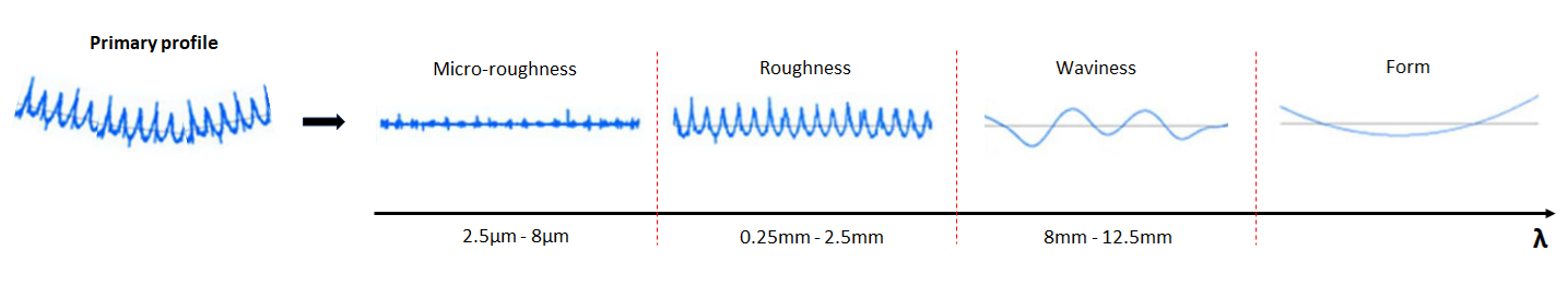
From a primary profile, we can extract this profile into micro-roughness, roughness, waviness and form. From these different components, we can calculate parameters to understand their conditions.
Primary profile is a profiled ta that has been filtered out its shortest wavelength component. Usually, if we obtain a profile data by using a stylus (contact instrument), we directly get the primary profile of a measured surface.
Because the stylus tip acts as a morphological filter that wipes out the shortest components (may be due to high frequency electronic noises from a measuring instrument).
If the profile is obtained from sectioning a 3D areal data captured by an optical measuring instrument, there is a process to obtain the primary profile from the data. A low pass filter with cut-off length usually 2.5micrometre is applied to simulate a morphological filter from a stylus tip.
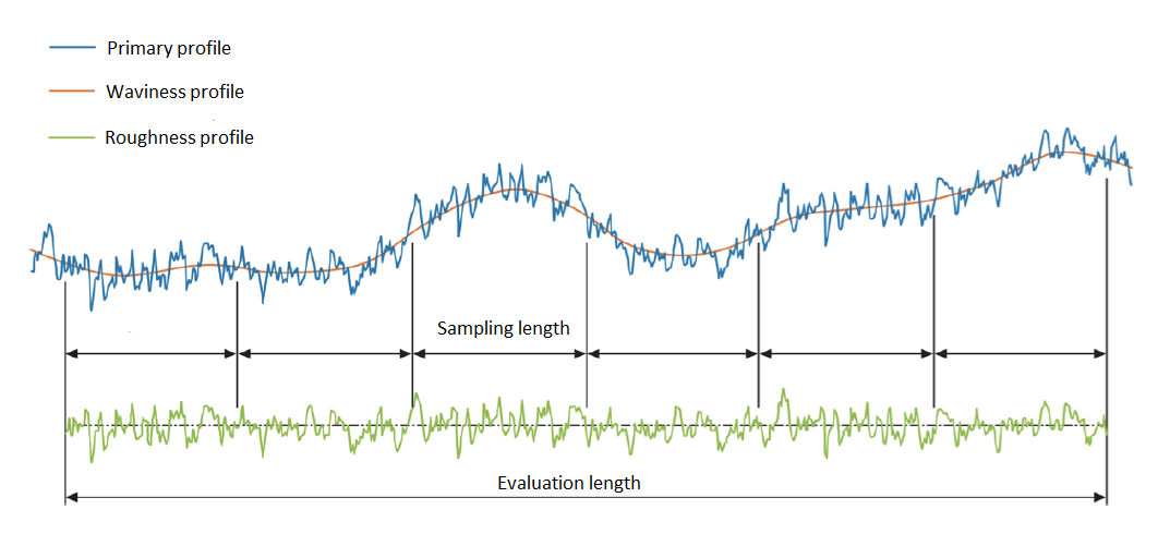
Figure 2 below shows an illustration of different components on the traced profile of a measured surface. From this figure, the roughness profile is approximately flat because we have removed the form and other low frequency components from the primary profile data.
3D areal surface components
Areal surface data initially obtained by using a 2D stylus (contact) instrument taking consecutively a single line profile at different section of a surface with constant step side.
Hence, this collection of many single line trace profiles becomes and areal surface data.
Since, we get these data from a stylus (contact) instrument, the areal data we get is directly a primary areal data since the high-frequency components data has been filtered out by the stylus tip.
Nowadays, non-contact measuring instruments (such as focus variation microscopy and point auto-focus) emerge as preferred instrument to measure areal surface. In this case, we need to remove the high-frequency components by applying a low-pass filter with cut-off length typically of 2.5micrometre.
Similar to 2D profile data, we must apply filtering processes to separate an areal surface data into different components of areal roughness, areal waviness and the surface form.
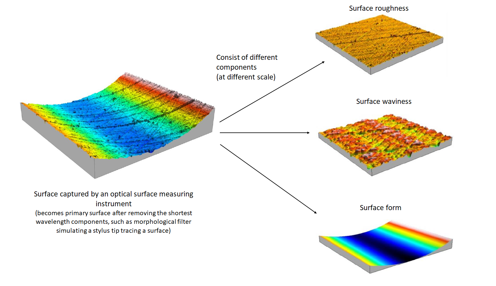
Figure 3 below shows an example of a 3D areal surface data with its components (roughness, waviness and surface form) after we apply different filters.
READ MORE: Five reasons why measurement uncertainty is important
Why do we need to measure surfaces?
Surface texture measurement is important due to at least several reasons.
Firstly, surface texture is the first thing in a part that we as human can feel. From feeling this surface, we can have perceptions about the part, such as whether the part is very smooth as a sign of a very high-quality polishing process or the part has some specific rough texture as desired for supporting surface glue.
Secondly, many products require surface contacts to deliver functionalities, such as piston and cylinder block, bushing, sideways guide and others.
Thirdly, advanced products require specific engineering surface texture with not only have specific roughness but also has specific micro-scale features to deliver advance engineering features [3].
There are many real examples of the importance of surface texture with respect to the functionality of the surface and the whole assembled product, such as friction reduction, corrosion resistance, wettability, adhesion, self-lubricating, aerodynamic drag behaviour, heat transfer, water repulsion, wear resistance, increase fatigue strength, dumping, gripping, sealing and many other functionalities.
Some examples are as follows.
In automotive components, nowadays, industries intentionally design and engineer the surface of a piston and cylinder block such that the surface has deterministic valley features. These valleys are design as reservoir to store lubricant to significantly reduce frictions between the piston and cylinder block surface. This deterministic engineering surface is made possible with the advance of manufacturing process, such as micro laser surface texture machining.
In medicine, the surface of a biocompatible metallic implant requires strictly controlled surface texture roughness. Because the surface roughness directly affects the tissue adhesion and osteo integration.
In consumer products, the surface of the touch screen of an electronic device requires specific surface texture to provide anti-glare coating. With this coating, users will have a significant improvement on the usability of the touch screen.
In aerospace engineering, the surface texture of turbine blades has a direct effect on the aerodynamic behaviour of the turbine blades.
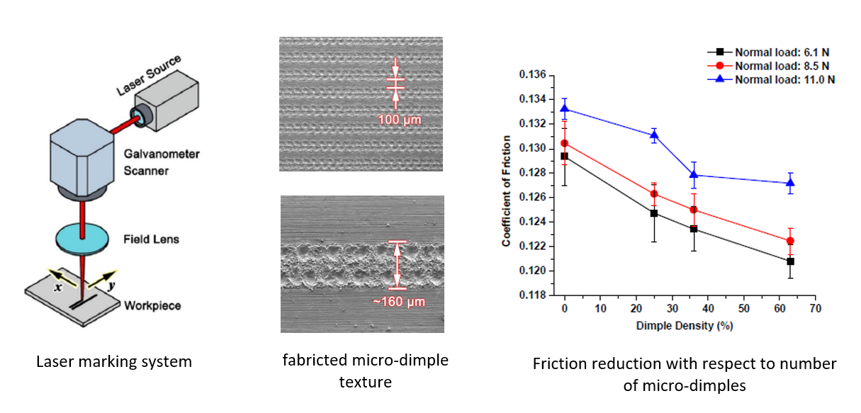
A case study has been presented in [4] about the effect of engineered micro-dimpled surface texture can control the surface friction properties. In this case study, the micro-dimpled is engineered to collect and store lubricant and hence to reduce frictions.
The manufacturing process to produce the micro dimpled structures is a micro-scale laser marking system.
Figure 4 below presents the schematic view of the laser marking system, the produced micro-dimpled texture and the reduction on friction due to the surface has the micro-dimpled texture.
In Figure 4, the micro dimples have a diameter of around 80micrometer (160micrometer per two dimples).
From test results [4], the more micro dimple density a surface has, the more friction reduction the surface can provide.
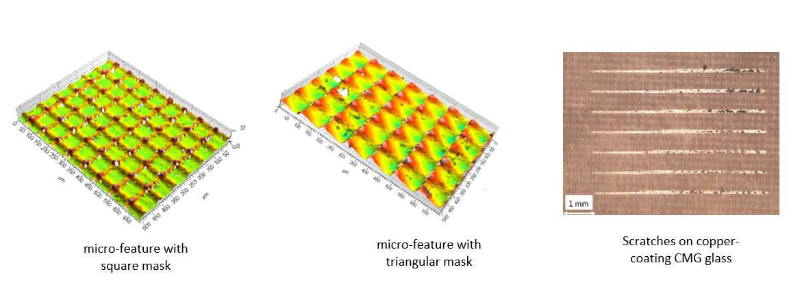
Another example of studying the correlation between the texture of an engineered surface and its mechanical bond strength has been reported in [5].
The studied surface textures are the electroless copper plating of CMG glass substrates. A micro-scale excimer laser machining produces the micro engineered textures. The engineered texture are square and triangular geometries.
Scratching to identify critical load failures (the adhesive bond failure) are applied to the engineered surfaces. These surfaces are characterised by areal surface parameters which are Spc, Sq, VVc and Sdq [6].
From the test results, those parameters have high correlation with the mechanical bond strength of the surfaces. For Spc, Sq, VVc and Sdq parameters, the Pearson correlation with respect to the bond strength are -0.81, -0.76, -0.75, -0.73 respectively.
From these Pearson correlations, the areal parameters of the engineered surfaces have inverse proportional to the bond strength [5].
Figure 5 below shows examples of engineered surfaces with square and triangular micro features. In addition, the results of several scratch tests show different degradations under different scratch loads.
Different micro feature geometries have different impacts on resistance from scratches due to different friction interactions. From this study, with the advances of micro-scale manufacturing processes and surface texture measuring instruments, ones can deterministically design a surface which has tailored functionalities.
Factors affecting surface texture
There are factors substantially affect surface textures, some of them are as follows:
- Types of manufacturing processes.
There are many types of manufacturing processes, such as subtractive processes (including milling, turning, grinding, polishing), additive manufacturing and forming processes.
Each process will have their “manufacturing signatures” resulting in specific surface textures such as rough or smooth surfaces or surfaces with deterministic features. For example, polishing processes will produce significantly smoother surface than grinding processes.
- Parameters of manufacturing processes.
Within a type of manufacturing processes, different parameters will yield to different surface finishes. For example, in milling processes, the same process one with high spindle speed, low depth of cut and another one with low spindle speed and high depth of cut will produce totally different surface textures. The first one will produce smoother surface than the last one.
- Properties of workpieces.
Also, within the same manufacturing process and the same process parameter, when we apply the process to different type of materials, the process will give different surface textures on the finished parts.
READ MORE: How to correctly present a measurement result
Standard for 2D profile and 3D areal surface texture measurements
Both 2D profile and 3D areal surface texture related measurements, data processing and filtering, there have been already established standards.
Standards related to 2D profile roughness are as follows:
- ISO 3274:1996 Geometrical Product Specifications (GPS) — Surface texture: Profile method — Nominal characteristics of contact (stylus) instruments.
- ISO 4288:1996 Geometrical Product Specifications (GPS) — Surface texture: Profile method — Rules and procedures for the assessment of surface texture.
- ISO 4288:1996 Geometrical Product Specifications (GPS) — Surface texture: Profile method — Rules and procedures for the assessment of surface texture.
- ISO 16610-21:2011 Geometrical product specifications (GPS) — Filtration — Part 21: Linear profile filters: Gaussian filters.
- ISO 12085:1996Geometrical Product Specifications (GPS) — Surface texture: Profile method — Motif parameters.
- ISO 13565-1:1996 Geometrical Product Specifications (GPS) — Surface texture: Profile method; Surfaces having stratified functional properties — Part 1: Filtering and general measurement conditions
- ISO 13565-2:1996 Geometrical Product Specifications (GPS) — Surface texture: Profile method; Surfaces having stratified functional properties — Part 2: Height characterization using the linear material ratio curve.
- ISO 13565-3:1998 Geometrical Product Specifications (GPS) — Surface texture: Profile method; Surfaces having stratified functional properties — Part 3: Height characterization using the material probability curve.
- ISO 5436-1:2000 Geometrical Product Specifications (GPS) — Surface texture: Profile method; Measurement standards — Part 1: Material measures.
- ISO 5436-2:2012 Geometrical product specifications (GPS) — Surface texture: Profile method; Measurement standards — Part 2: Software measurement standards.
- ISO 12179:2021 Geometrical product specifications (GPS) — Surface texture: Profile method — Calibration of contact (stylus) instruments.
- ISO 1302:2002 Geometrical Product Specifications (GPS) — Indication of surface texture in technical product documentation.
Standards related to 3D areal surface texture are as follows:
Meanwhile, for 3D areal surface, the standard is mostly unified in a single standard ISO 25178 series. Inside this standard series, there are sub standards that guides from filtering, parameters to surface texture measuring instruments.
- ISO 25178-1:2016 Geometrical product specifications (GPS) — Surface texture: Areal — Part 1: Indication of surface texture.
- ISO 25178-2:2012 Geometrical product specifications (GPS) — Surface texture: Areal — Part 2: Terms, definitions and surface texture parameters.
- ISO 25178-3:2012 Geometrical product specifications (GPS) — Surface texture: Areal — Part 3: Specification operators.
- ISO 25178-6:2010 Geometrical product specifications (GPS) — Surface texture: Areal Part 6: Classification of methods for measuring surface texture.
- ISO 25178-70:2014 Geometrical product specification (GPS) — Surface texture: Areal — Part 70: Material measures.
- ISO 25178-71:2012 Geometrical product specifications (GPS) — Surface texture: Areal — Part 71: Software measurement standards.
- ISO 25178-72:2017 Geometrical product specifications (GPS) — Surface texture: Areal Part 72: XML file format x3p.
- ISO 25178-600:2019 Geometrical product specifications (GPS) — Surface texture: Areal Part 600: Metrological characteristics for areal topography measuring methods.
- ISO 25178-601:2025 Geometrical product specifications (GPS) — Surface texture: Areal — Part 601: Design and characteristics of contact (stylus) instruments.
- ISO 25178-602:2025 Geometrical product specifications (GPS) — Surface texture: Areal Part 602: Design and characteristics of non-contact (confocal chromatic probe) instruments.
- ISO 25178-603:2025 Geometrical product specifications (GPS) — Surface texture: Areal Part 603: Design and characteristics of non-contact (phase shifting interferometry) instruments.
- ISO 25178-604:2025 Geometrical product specifications (GPS) — Surface texture: Areal — Part 604: Design and characteristics of non-contact (coherence scanning interferometry) instruments.
- ISO 25178-605:2025 Geometrical product specifications (GPS) — Surface texture: Areal — Part 605: Design and characteristics of non-contact (point autofocus probe) instruments.
- ISO 25178-606:2015 Geometrical product specification (GPS) — Surface texture: Areal Part 606: Nominal characteristics of non-contact (focus variation) instruments.
- ISO 25178-607:2019 Geometrical product specifications (GPS) — Surface texture: Areal Part 607: Nominal characteristics of non-contact (confocal microscopy) instruments.
- ISO 25178-700:2022 Geometrical product specifications (GPS) — Surface texture: Areal Part 700: Calibration, adjustment and verification of areal topography measuring instruments.
- ISO 25178-701:2010 Geometrical product specifications (GPS) — Surface texture: Areal Part 701: Calibration and measurement standards for contact (stylus) instruments.
Surface texture optimisation
There are several considerations when we want to optimise surface finishes for our applications at hand. Some of them are as follows [7]:
- Surface functionality.
We need to define the main purpose of our products.
For example, for engineering purpose, we need functional surface with special deterministic micro features to reduce frictions or increase bonding strength or other needs. Or maybe we just need an aesthetic surface that only require a general smoothness instead of specific engineered features
- Material compatibility.
Different materials will have different interaction behaviours such as adhesion behaviours and corrosion behaviours. For example, with the same surface texture characteristics, stainless steel will have higher corrosion resistance with respect to cast iron.
- Surface roughness.
Roughness, both 2D profile and 3D areal surface, is well-known as one of the main parameters to characterise surfaces. There are many parameters, both for profile and areal roughness, such as Ra, Sa, Rq, Sq and other parameters.
- Manufacturing processes.
We have previously discussed manufacturing processes will have a direct impact on resulted surface texture. Every manufacturing process will have their “manufacturing signature” which is unique.
This signature will dictate the final surface texture we will get from a specific manufacturing process.
- Industry standard.
We need to comply with industry standard (for example, ISO25178 series, ISO4287, ISO4288, ISO16610 series and other standards) when we design and verify surface textures. One of the advantages is to have global acceptance of our surface texture data.
- Cost/budget limitation.
To get a specific surface texture to satisfy our needs, we should consider our allowable budget. This budget will constraint our selection of manufacturing processes and inspection of our engineered surfaces.
- Expert consultancy.
We must constantly engage with the surface texture community including engineer, scientist, governing body, academia and private industries to always have information exchange and constructive collaborations to address new challenges in surface texture design, manufacturing and inspection for new special and advanced engineering applications.
READ MORE: Measurement uncertainty estimations: GUM method
CAD symbols for surface texture
Like GD&T symbols, we also need to describe roughness tolerances or limits on a computer-aided design (CAD) technical drawing.
ISO 21920 provided the guide for symbols used to represent roughness tolerances of surfaces on technical drawing [8].
Figure 6 below presents the main symbols of roughness tolerance on CAD technical drawing. From this figure, there are mainly three types of symbols to control the manufacturing processes and material removals, which are any manufacturing processes, material shall be removed and material shall not be removed.
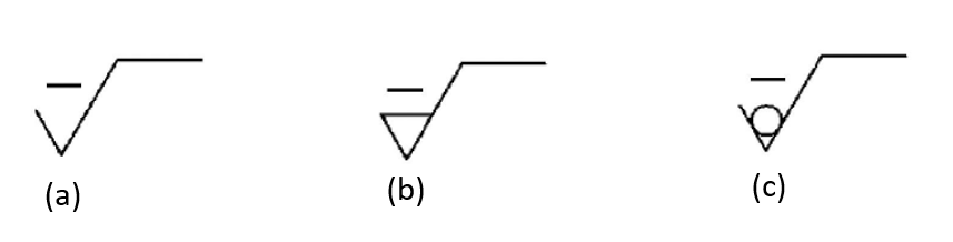
From this ISO 21920 standard, it suggests the standard only focuses on 2D profile parameters, but the symbols still lack in focus for 3D areal parameters, especially on how to represent and tolerance areal feature parameters on technical drawing [2].
Hence, standardisation organisations need working on developing 3D areal parameter and tolerance symbols on CAD.
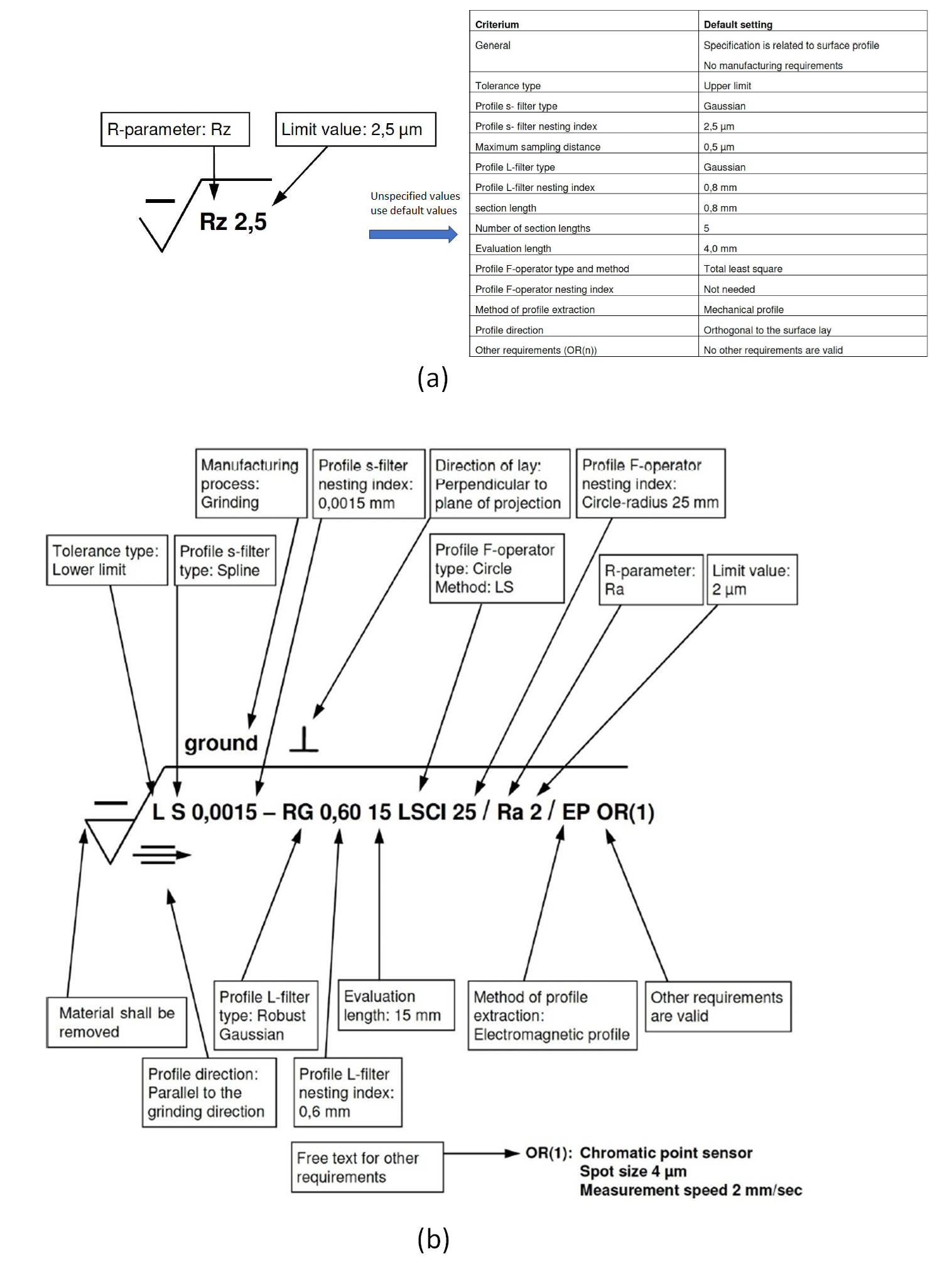
There are two ways of using the roughness CAD symbols: using default values for undefined parameters or explicitly defining all parameters without using default values.
Figure 7 shows the two ways of using CAD symbol for roughness.
From figure 7, the first type if only define specific parameters on the symbols (figure 7a) while all their parameters use default pre-determined values (figure 7b). The second type is where we explicitly define al parameters (this option is less likely to be chosen since it will make the symbol to be completed on a technical drawing).
READ MORE: Measurement uncertainty estimations: Monte-Carlo simulation method
Conclusion
In this post, we have described the main importance and motivation of why surface texture measurement is as important as dimensional and geometrical measurement.
Both dimensional/geometrical and surface texture measurement complement each other.
In geometrical measurement, we focus on making sure the form/shape of a part is within tolerance so that we can assemble the part as per its design intent.
Meanwhile, in surface texture measurement, we want to assure that a part can deliver its function as desired. For example, the surface of a piston and engine block should be specifically engineered to improve lubrications on both surface such that we can get a large friction reduction for the engine can work smoothly.
Also, we have discussed two different types of surface texture measurements: 2D profile and 3D areal measurements. Note that we calculate surface texture measurement parameters at specific scale (roughness, waviness of primary components) of the surface.
We have discussed two examples of why engineered surfaces (a surface with a designed deterministic features) can deliver a specific functionality to satisfy unique applications at hand, such as increasing mechanical bond strength or reducing frictions between two contacting surfaces.
Importance ISO standards governing both 2D profile and 3D areal surface texture measurements have been presented for user’s guide references.
Finally, we also discussed factors affecting surface texture, how to optimise surface texture and CAD symbols to represent surface texture requirement and tolerance on 2D technical drawing.
Reference
[1] ISO 17450-1:2011, Geometrical product specifications (GPS) — General concepts Part 1: Model for geometrical specification and verification.
[2] ISO 25178-2:2021, Geometrical product specifications (GPS) — Surface texture: Areal Part 2: Terms, definitions and surface texture parameters.
[3] Leach, R. ed., 2013. Characterisation of areal surface texture. Berlin: Springer.
[4] Wei, Y., Resendiz, J., Tomkowski, R. and Liu, X., 2021. An experimental study of micro-dimpled texture in friction control under dry and lubricated conditions. Micromachines, 13(1), p.70.
[5] He, B., Petzing, J., Webb, P., Conway, P. and Leach, R.K., 2012. The use of areal surface texture parameters to characterize the mechanical bond strength of copper on glass plating applications. N{L Report.
[6] ISO 25178-2. Geometrical Product Specifications (GPS) – Surface texture: Areal – Part 2: Terms, definitions, and surface texture parameters. 2012.
[7] Tomkowski, R. 2025. Surface characterisations. KTH Stockholm.
[8] ISO 21920-1:2021 Geometrical product specifications (GPS) — Surface texture: Profile — Part 1: Indication of surface texture
You may find some interesting items by shopping here.