True position deviation in Geometric dimensioning and tolerancing (GD&T)
In this post, we will discuss exclusively about true position tolerance: the allowed and actual position deviation and the concept of designing a hole and pin for mating purpose with the concept of virtual boundary.

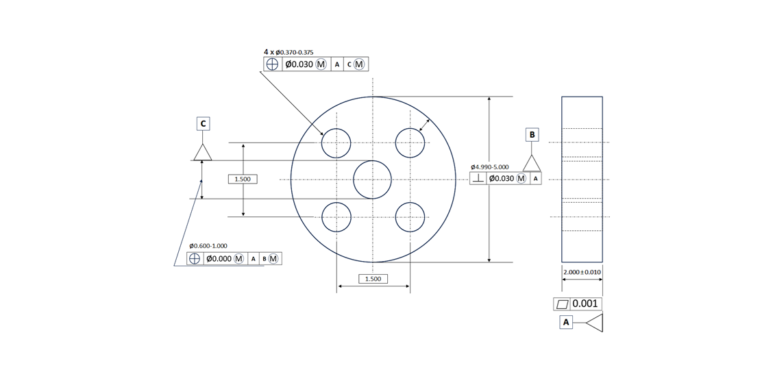
Pin/shaft (external feature of size) and hole (internal feature of size) are the two most important features on parts. Because pin/shaft and hole are assembly features where a part can mate or contact its counterpart [1].
In this post, we will discuss exclusively about true position tolerance: the allowed and actual position deviation and the concept of designing a hole and pin for mating purpose with the concept of virtual boundary [2].
Position tolerance means that the measured axis of a manufactured shaft or hole must lie within the cylindrical tolerance zone of a given position tolerance.
That is, position tolerance is the allowed deviation from true position specified in the 2D drawing.
When there is an MMC symbol of the datum feature frame, there will be a bonus position tolerance. This bonus tolerance relaxes an allowed deviation drawn from the size (diameter) of a hole or pins when the hole or pin deviate from their MMC toward their LMC [3][4].
In a short word, the tolerance growth when a feature of size departs from its (maximum material condition) MMC toward its LMC (minimum material condition) size.
For a hole (internal feature of size), MMC is the smallest allowed hole diameter and LMC is the allowed largest hole diameter.
Meanwhile, for a pin/shaft (external feature of size), MMC is the largest allowed pin diameter and LMC is the smallest allowed pin diameter.
Every MMC or LMC symbol in a 2D drawing tells a story (from the designer of the part) to an inspector in a quality inspection process about the characteristics of feature of size for conformance of desired functionality.
To have a complete story, datums and feature control frames give the story completeness for the inspector to make a correct judgment and recommendations about a part quality.
The recommendations include feedback to the manufacturing processes of the part to improve the part quality while minimising cost.
In addition, we will also discuss on how to design the mating pin on a hole using the virtual boundary concept.
READ MORE: Understanding fundamental assembly features: Mate and contact features
This mini plier combination set is the perfect everyday carrier that can fit in a small space. They can be used to fix most of daily assembly/disassembly problems

True position inspection process
In this section, we will discuss the basics on how a true position tolerance is inspected.
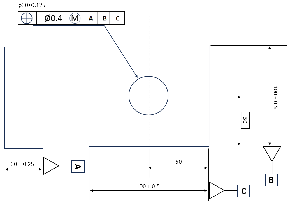
For clarity, let’s discuss it with a simple plain example of a position tolerance as shown in figure 1.
In figure 1, a simple block with a hole feature is designed. The hole is toleranced with a position tolerance of Xmm.
There are three datums A, B and C. Datum A is the top surface of the part. Meanwhile, datum B and C are the side plane at the bottom and right side (with respect to figure 1 view).
After the designed part is produced, we need to verify the position of the hole feature as per its drawing. We perform the verification by calculating how far the hole’s axis deviates from datum B and C.
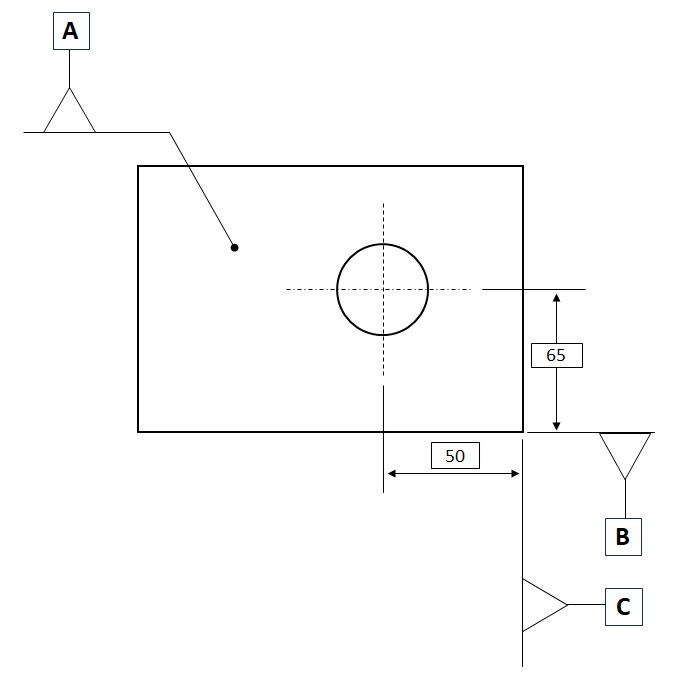
To verify the true position tolerance on the part (show in in figure 1), we need to measure the maximum deviation point of the hole’s axis from both datum B and datum C.
Let’s say we measure the largest axis distance from datum C (along X-axis) to be 50.2mm. Meaning, there is 0.2mm deviation of the axis position from its true position of 0.2mm from datum C.
Also, let’s say we measure the largest axis distance from datum B (along Y-axis) to be 65.1mm yielding to the 0.1mm maximum deviation of the true position from datum B.
Hence from these two largest radial deviations of the axis from its designated true position, we can calculate the hole axis deviation to be:

Since what we are interested is on the diameter of deviation around the true position of the hole axis, we then multiply the axis’ radial deviation by 2.
Hence, the final calculated true position deviation is as follows:
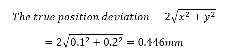
We then compare this computed true position deviation of 0.446mm against the allowed deviation of Xmm following the technical drawing specification.
If the allowed deviation (that is, the cylindrical tolerance zone diameter) is larger than the computed true position deviation of 0.446mm. hence, we can claim that the hole axis’ deviation is within its tolerance.
Otherwise, we must reject the part and must repair or scrap it.
Here is the interesting point if allowed deviation is smaller than the true position deviation, the decision of repair (rework) or scrap can be determined by the material modifier symbol on a technical drawing.
- If the symbol is MMC, meaning, there will be bonus when the hole diameter is made larger (deviate from its MMC to the LMC size). Hence, with the bonus tolerance we may accept the part.
- If the symbol is LMC, if the whole is not made at LMC (its largest diameter), we can repair the hole by a drilling process to enlarge the hole diameter. By doing this, we will not scrap the hole.
Note that if the tolerance zone is spherical, hence the true position formulation becomes:

Note that this is the process of how a true positions is verified. When we use a coordinate measuring machine (CMM) instrument, the true position verification will be calculated automatically given the probed points of the datum and hole surfaces.
READ MORE: 3D tolerance stack-up analysis with examples
Virtual boundary to design mating feature of size
In this section, we will discuss on how to calculate allowed position deviation and the reasoning behind the allowed deviation.
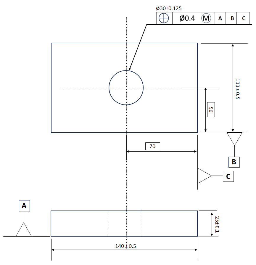
For this discussion, we will be using a technical drawing shown in figure 2 as case study.
In figure 2, the case study consists of a prismatic part with a single hole at the middle. Datum A is the base surface of the part. Datum B and datum C are the right and bottom side surface of the part, respectively.
The hole has a position tolerance about 0.4mm with MMC modifier symbol.
The main goal is we want to judge whether the hole on the part is in- or out-tolerance. And, if the hole is in-tolerance, we must sure that the hole functionality to mate is guaranteed.
To inspect the part, an inspector in a quality inspection department must understand the design intent of the inspected part.
GD&T symbols, in this case position tolerance, convey the message from the part designer to the inspection.
That is, the inspector must carefully understand the given tolerance on the drawing and get the conveyed message from the part designer on how the part should function or operate.
The conveyed message is represented by the datum symbols (Datum A, B and C) and the feature control frame containing the position tolerance and its modifier, in this case the MMC symbol "M".
From the GD&T symbol, we can interpret the hole in figure 2 to be as follows.
“The hole should mate with its counterpart (pin or shaft) when the part is seated at surface A (Datum A) and the hole location is 50mm from Datum B and 50mm form datum C. The datum B and C should be perpendicular to datum A. In addition, the axis of the hole may be deviate within a cylinder with diameter of 0.4mm from its true position when the hole is made as the smallest allowable diameter (at MMC condition). If the hole is made larger from its MMC diameter (the smallest allowable diameter) towards its LMC diameter (the largest allowable diameter), then the axis can deviate to be 0.4mm+bonus tolerance. “
- The next question is, what is the condition of a pin or shaft that can mate with the given hole shown in figure 2 above?
- What is the allowable largest pin or shaft that can enter (mate with) the hole at a desired angle from datum A ,B, C when the hole is made in its MMC or depart from MMC to LMC?
To answer these questions, we must calculate the virtual boundary of the hole. This virtual boundary is the representation of the pin or shaft to enter or mate with the hole. The virtual boundary is a perfect cylinder, perfectly oriented with respect to datum A and perfectly located form datum B and datum C.
If the hole is made is outside this virtual boundary, the hole (internal feature) can accommodate its counter pin or shaft. That is, the size and position tolerance of the mating pin or shaft (external feature) of the hole should be designed, dimensioned and toleranced to reside within the virtual boundary.
By these principles when the part inspector accepts the part as within tolerance. It is with a confidence that the inspected feature (in this case hole) will work when being assembled.
To determine the virtual boundary of the hole, we can follow this formula (for internal feature such as hole):

In this case the virtual boundary of the hole is 29.875 – 0.4 = 29.475mm.
That is, when the hole is made larger towards its LMC size (the allowed largest diameter), hence there will be bonus tolerance as follows:
- Case 1 (hole at MMC size): 29.875 – 0.4 = 29.475mm
- Case 2: 30-(0.4+bonus) = 30-(0.4+0.125) = 29.475mm à bonus tolerance 0.125mm
- Case 3 (hole at LMC size): 30.125-(0.4+bonus) = 30-(0.4+0.25) = 29.475mm à bonus tolerance 0.25mm
From the calculations, we can see that the virtual boundary remains constant regardless the variation of the hole’s diameter and geometrical tolerances (due to bonus).
We can express as if the hole resides outside its virtual boundary of 29.475mm, the hole will mate with the worst case of its counter pin/shaft if the pin/shaft do not violate the virtual boundary condition (reside inside the virtual boundary).
That is, if the hole resides outside of the virtual boundary and the counter pin/shaft resides inside of the virtual boundary, the hole can mate with the pin/shaft without any material interferences.
READ MORE: Geometric dimensioning and tolerancing: Datum selection
Real practical example of virtual boundary
In this section, we will discuss a practical example of a true position tolerance as per drawing specification and as produced.
For this example, we will use the 2D drawing shown in figure 3 below.
In figure 3, we have a prismatic part with a hole in the centre. The primary datum A is on the base surface and the secondary (Datum B) and tertiary (Datum C) are on the bottom and side surface respectively.
The hole is position toleranced for 0.4mm with MMC modifier. The function of the hole is for accommodate a pin to mate with the part (for contact purpose).
Assuming that after manufacturing the part, we measure the produced hole to have a diameter of 30.1mm.
To decide whether we accept or reject this part, we need to calculate the virtual boundary of the hole.
The virtual boundary of the hole is the smallest allowed diameter (MMC) – position tolerance = 29.875-04=29.475mm.
Since, the produced part is 30.1mm>29.475mm (the hole’s virtual boundary is protected) and the 30.1mm is still in the allowable diameter size for the hole. Hence, we can accept the part.
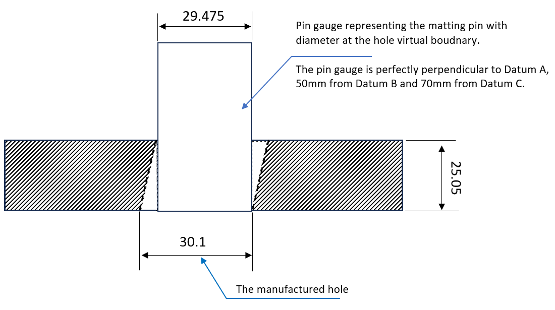
The illustration of how this produced part can provide its function to accommodate its mating pin, we can refer to figure 4 below.
In figure 4, the produced hole in reality will be not perfectly perpendicular with respect to Datum A (the bottom surface).
Meanwhile, the mating pin is represented by a high-precision pin gauge, with diameter of 29.475mm (the hole’s virtual boundary), located precisely to be perpendicular to Datum A, 50mm from Datum B, 70mm from datum C.
In this case, since the hole is made larger than the virtual boundary size of 29.475mm and hence, the pin gauge can still enter the hole. By this, we can simulate and confirm the assembly process of the hole with its mating pin.
READ MORE: General benefits when the variation transformation chain of an assembly is known
Conclusion
In this post, we discuss in detail the concept of true position tolerance and how to verify this tolerance.
We begin with the basic explanation of true position tolerance and how the fundamental procedure to verify this tolerance is applied.
We also discuss the concept of virtual boundary (in this case for hole as internal feature). This virtual boundary is important to design the mating pin of a hole with true position tolerance.
Finally, a practical example of part design with true position and how to inspect the manufactured part in practice with a pin gauge.
Reference
[1] Whitney, D.E., 2004. Mechanical assemblies: their design, manufacture, and role in product development. New York: Oxford university press.
[2] ASME Y14.5-2009, Dimensioning and Tolerancing: Engineering Drawing and Related Documentation Practices.
[3] Meadows, J.D., 2017. Geometric Dimensioning and Tolerancing: Applications and Techniques for Use in Design: Manufacturing, and Inspection. Routledge.
[4] Fischer, B.R., 2004. Mechanical tolerance stack-up and analysis. CRC Press.
If you want to support me developing this blog, you can support me here.
This Were screwdriver set is good for everyday carrier and can help finishing many assembly/disassembly jobs.