Geometric dimensioning and tolerancing (GD&T) and assembly of non-rigid parts
For non-rigid part assembly, the fixturing force will be relevant and needs to be considered carefully in their assembly design.
Geometric dimensioning and tolerancing (GD&T) is commonly performed on a rigid part where the effect of the fixturing force and spring-back are very often negligible. However, for non-rigid part assembly, the fixturing force will be relevant and needs to be considered carefully in their assembly design.
There are many applications for non-rigid part assembly. For example, the assembly of aeroplane fuselage and wing, the assembly of automotive body and the assembly of flexible components, such as cables and hoses.
In this post, we will give some perspectives for non-rigid part assemblies and the relevance of GD&T in these types of assembly.
READ MORE: Geometric dimensioning and tolerancing (GD&T)

Non-rigid assembly of automotive body
Non-rigid components are part components that can be easily deformed. Usually, these parts have a thin-walled body or made by non-rigid materials, such as plastics.
Common examples are automotive body parts, cables and hose and other sheet-metal components. In general, the assembly of these non-rigid bodies are more difficult compared to the assembly of rigid parts.
Because, in non-rigid part assemblies, spring-back effects are relevant and needs to be considered in designing their assembly process and analysing their GD&T tolerance stack up.
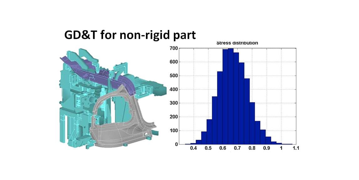
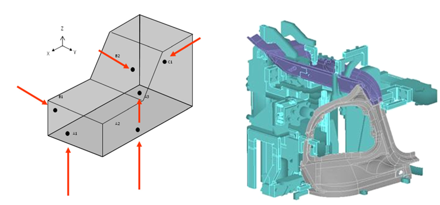
Figure 1 below shows an example of an automotive body assembly. For automotive body assembly, the fixturing should strictly follow the 6-point contact fixturing to avoid any over constraint that will cause additional force and deformed car body parts.
Figure 1 left shows the illustration of the 6-point fixture and figure 1 right shows an example of the implementation of the fixture concept into a car door body assembly. As can be seen, the fixturing implementation will be more complex than the concept as, in practice, car bodies have complex features.
The analysis of the tolerance chain is needed to be able to help designing the best fixture for a given body parts and analyse the effect of the spring-back force toward a final dimension of interest.
The paper in [1] has proposed a statistical control chart method that is able to monitor variations originated from fixture and from manufacturing process. By being able to separate these sources of variations on a car body assembly, the analysis of problem of an assembly key characteristic (KC)can be analysed and the solution can be proposed systematically.
READ MORE: Assembly and tolerancing
Non-rigid assembly of flexible cables and hoses
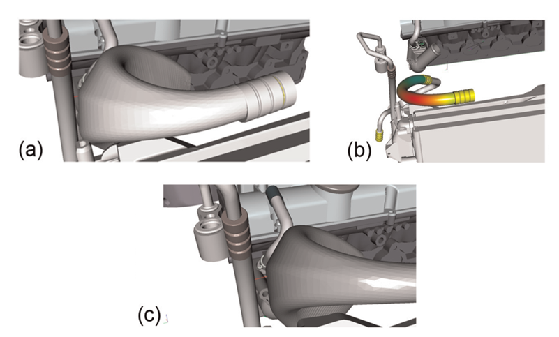
Figure 2 below shows an example of assembly design and simulation of a hose assembly [2]. A hose is a flexible part that is made of non-metal parts, commonly plastic or rubber. These plastic and rubber materials have a large thermal expansion coefficient compared to metal parts.
Hence, these type of plastic and rubber parts will significantly expand in high temperature environment.
From figure 2, the assembly process simulation to estimate the shape variation of the hose due to thermal expansion is presented. The initial design of the hose shows that when the hose expands at its working temperature, the shape of the hose due to the expansion will touch the vertical pipe, that is hot (in figure 2 left), and then will be damaged.
After a redesign of the hose, from the variation and tolerance simulation, when the hose expands at its working temperature, the hose will not touch the vertical pipe and will not be damaged by the heat of the vertical pipe. From this case, it can be observed that designing the assembly and shape of flexible parts is not easy, or at least more difficult compared to rigid parts.
READ MORE: Understanding fundamental assembly features: Mate and contact features
- Assembly Automation and Product Design – A book about how to correctly design a product that is suitable for assembly automation.
The analysis of assembly stress in composite assembly processes
The assembly of composite materials, such as in automotive car body and aeroplane body assemblies, contain a high assembly stress from the effect of the join of the composite parts during the assembly process [3].
Composite parts are characterised by high strength-to-weight ratio. This high ratio is one of the biggest contributions of high stress during their assembly processes.
The other difficulty of composite assemblies is that these parts are also brittle (not as ductile as sheet-metal parts). Hence, the assembly process should be strong enough to response to the required high assembly stress.
However, at the same time, the assembly force should not be too strong. Because it will cause the composite part to have a fracture or crack.
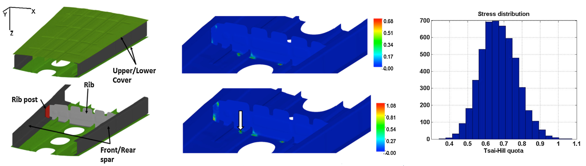
Figure 3 below presents the work in [3] to analyse the assembly stress for composite materials. Figure 3 left shows the assembly of two composite parts. The points where the high stress accumulated during the assembly process is shown in figure 3 middle. Finally, figure 3 right presents the stress distribution at the point locations after performing variation analyses of the assembly process of the components.
READ MORE: The economic benefits of tolerance stack-up analysis
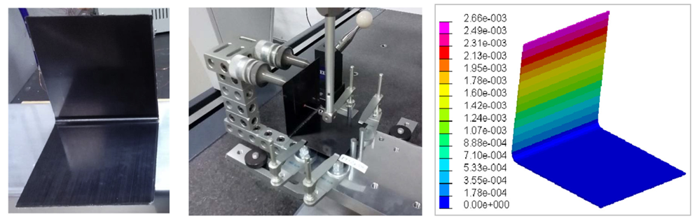
The spring-back effect on non-rigid part assembly
The spring-back effect in non-rigid assembly is very relevant and should be considered. A study to estimate the amount and effect of the spring-back force on a composite non-rigid part assembly has been reported [4].
In the report, the analysis tries to estimate the spring-back effect with regard to the angle deviation of flange-to-flange of a composite material.
Figure 4 below shows the study and analysis to estimate the angle deviation on a composite material. A high accuracy tactile coordinate measuring machine (CMM) is used to measure the flange-to-flange angle of the materials. The results of CMM measurements are then compared to the results from a finite element simulation method.
From the analysis, the angle deviation due to spring-back effect on the non-rigid composite part assembly is around 0.58 degree to 2 degree deviation. These values are very useful as inputs to the tolerance stack up analysis of the composite assembly.
READ MORE: How BMW reduces their assembly cost by optimising assembly features and fixturing constraints
- Assembly Automation and Product Design – A book about how to correctly design a product that is suitable for assembly automation.
Conclusion
In this post, non-rigid part assemblies are presented. The assembly of non-rigid parts are commonly more difficult compared to the assembly of rigid parts.
Because there are effects that are negligible in rigid-part assemblies but are relevant in non-rigid-part assemblies. For example, the effect from the spring-back force of non-rigid parts.
In this post, examples of non-rigid part assemblies, that are sheet-metal parts, composite and hose components, have been presented and discussed.
One important thing to remember is that, the deviation caused by the spring-back effect during the assembly of non-rigid parts should be quantified to be used as input for their tolerance stack up analysis to estimate their KC variations.
References
[1] Wärmefjord, K., Carlson, J.S. and Söderberg, R., 2016. Controlling geometrical variation caused by assembly fixtures. Journal of Computing and Information Science in Engineering, 16(1).
[2] Hermansson, T., Carlson, J.S., Björkenstam, S. and Söderberg, R., 2013. Geometric variation simulation and robust design for flexible cables and hoses. Proceedings of the Institution of Mechanical Engineers, Part B: Journal of Engineering Manufacture, 227(5), pp.681-689.
[3] Söderberg, R., Wärmefjord, K. and Lindkvist, L., 2015. Variation simulation of stress during assembly of composite parts. CIRP Annals, 64(1), pp.17-20.
[4] Bellini, C., Sorrentino, L., Polini, W. and Corrado, A., 2017. Spring-in analysis of CFRP thin laminates: numerical and experimental results. Composite Structures, 173, pp.17-24.
You may find some interesting items by shopping here.